

Data form having a position-coding pattern detectable by an optical sensor
a technology of position-coding pattern and data form, which is applied in the field of data form having a position-coding pattern detectable by an optical sensor, can solve the problems of difficult identification and deciphering of form entries, difficult automatic form recording, and complex image analysis software, etc., and achieve good resolution
Inactive Publication Date: 2002-05-02
ANOTO AB
View PDF19 Cites 80 Cited by
- Summary
- Abstract
- Description
- Claims
- Application Information
AI Technical Summary
Benefits of technology
The present application describes how certain coding patterns can be used to create a large area with high precision. These codes can help identify specific forms or documents based on their unique arrangement. Additionally, if the printing process is accurate enough, the actual locations of the code can also be identified by measuring the distance between them. Overall, this technology allows for better management and handling of paper documents.
Problems solved by technology
The technical problem addressed in this patent text needs to be identified by a senior R&D personnel.
Method used
View moreImage
Smart ImageViewing Examples

Examples
Embodiment Construction
, with each claim standing on its pwn as a separate preferred embodiment of the invention.
Login to View More PUM
 Abstract
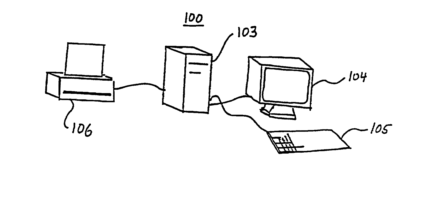
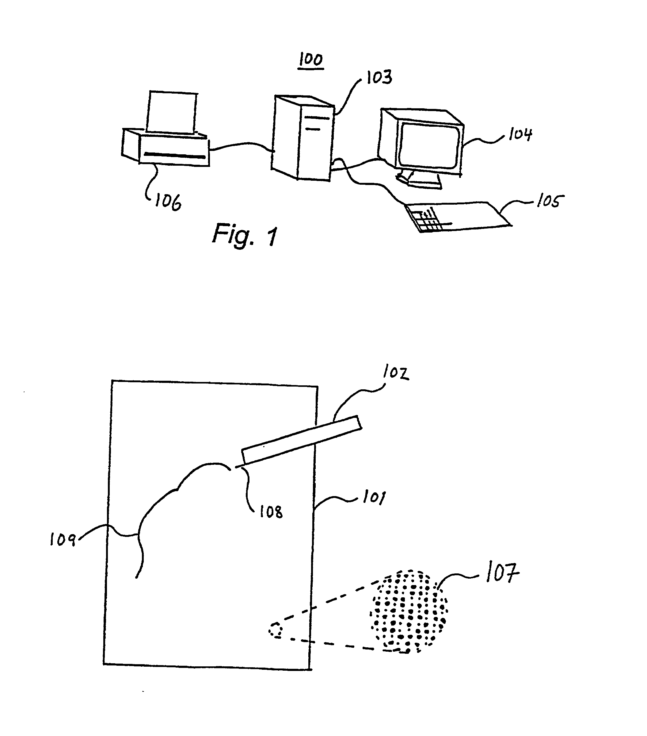
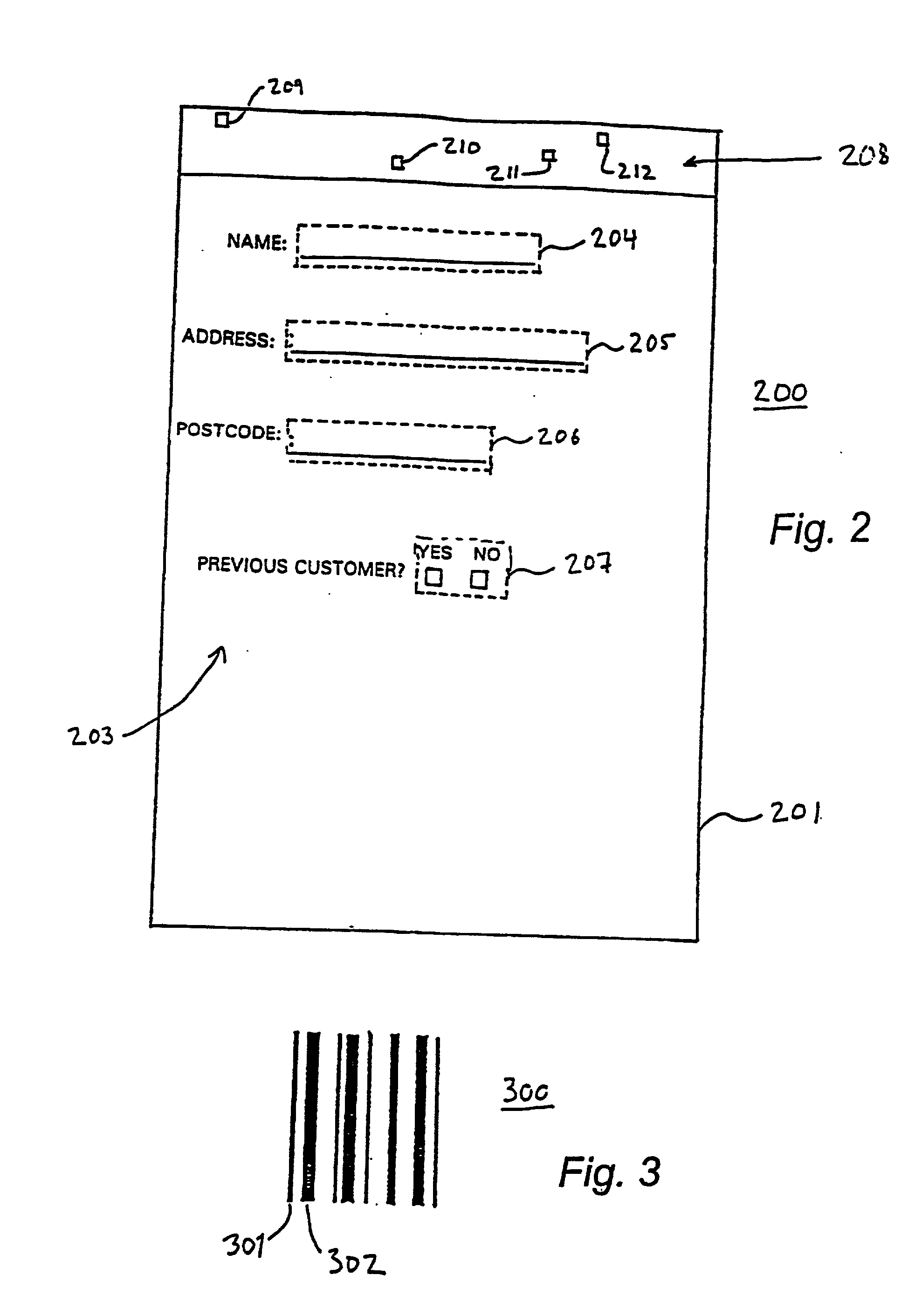
Disclosed is a form having a form layout with at least one entry field. It may be printed on a base in the form of a sheet (or any other surface). The surface of the base may have a position-coding pattern. The entry field can be completed using a user unit that has an optical sensor to detect positions on the sheet utilizing the position-coding pattern. The optical sensor can thereby enable digital recording of the information entered in the entry field. The surface may also have an identity pattern that can identify the form layout after recordation by the sensor of the locations defined by the identity pattern.
Description
Login to View More Claims
Login to View More Application Information
Patent Timeline
 OwnerANOTO AB