Joint on a spacecraft

a spacecraft and joint technology, applied in the field of joint, can solve problems such as inability to corr

Inactive Publication Date: 2002-07-11
SAAB ERICSON SPACE
View PDF0 Cites 3 Cited by
  • Summary
  • Abstract
  • Description
  • Claims
  • Application Information

AI Technical Summary

Problems solved by technology

The joint devices must be low-weight and be designed for very high reliability because of the extremely high cost of launching, as well as the impossibility of correcting any faults that may arise when the craft has left the ground.

Method used


Image

  • Joint on a spacecraft
  • Joint on a spacecraft

Examples


Embodiment Construction

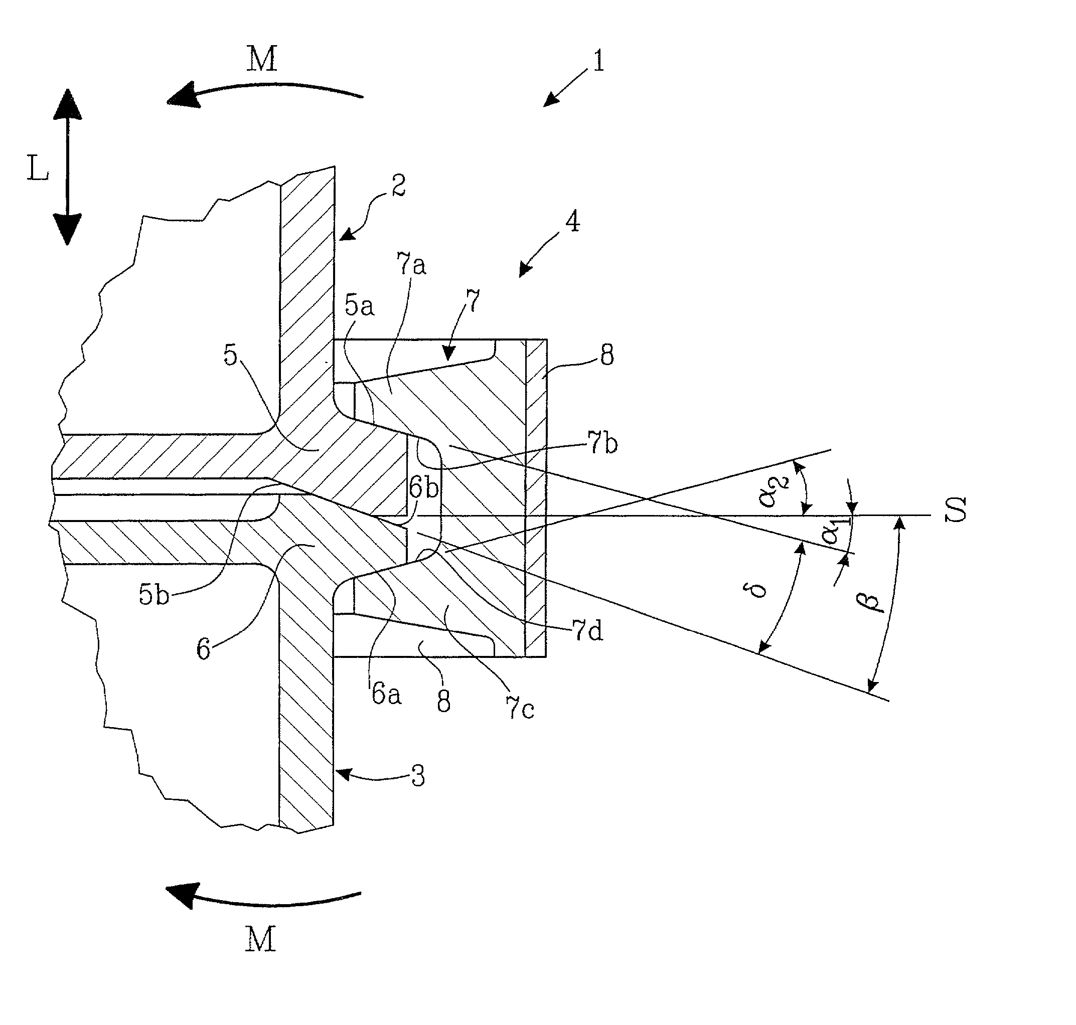
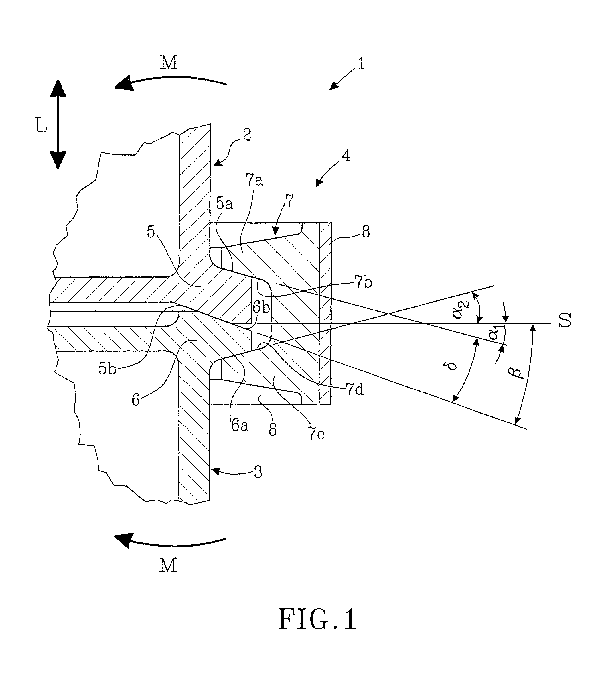
[0010] A spacecraft is indicated by 1 in the drawing. The spacecraft comprises two mutually detachable parts 2, 3, for example a satellite part 2 positioned on a carrier rocket 3, a so-called launcher part. A joint 4 is present to keep the two parts 2, 3 together during the time the joint is being used.

[0011] The joint includes a first flange 5 fixed at a lower part of the first craft part 2, and a second flange 6 fixed at an upper part of the second craft part 3. Furthermore, the joint 4 consists of one or more clamps 7 distributed around the periphery of the flanges 5, 6, and a tightening device 8, which extends around or through the clamps 7 and presses them radially inwards against the flanges 5, 6.

[0012] The clamps 8 are thus designed to transmit a radial force from the tightening device 8 to a clamping force, and to press the flanges 5, 6 against each other. To this end, the clamps 7 have a first clamp lip 7a with a first clamp surface 7b, and a second clamp lip 7c with a seco...


PUM


Abstract

A joint (4) on a spacecraft (1) for holding together a first craft part (2) and a second craft part, (3) detachable from the first craft part (2). The joint (4) comprises a first flange (5) fixed on the first craft part (2), and a second flange (6) fixed on the second craft part (3), and a number of clamps (7) having a first (7a) and a second (7c) clamp lip, the said clamps being distributed about the periphery of the flanges (5, 6). The clamps transfer radial forces from a tightening device (8), fitted to the clamps (7), so as to fasten the two flanges (5, 6) together. The first flange (5) is clamped between a first clamp surface (7b) on the first clamp lip (7a), and a separation surface (6b) on the second flange (6). These surfaces (7b, 6b) form an acute angle delta, the apex of which is directed in towards the spacecraft (1).

Description

[0001] The invention presented here relates to a joint for holding together detachable parts of a spacecraft, particularly during launching of the spacecraft. More specifically, the invention concerns a joint comprising a number of clamps, which by means of an encircling brace are pressed against flanges on the detachable components and thereby holding them together.BACKGROUND TO THE INVENTION AND THE PROBLEM[0002] Joint devices for connecting, without any significant relative movement, detachable parts of a spacecraft, for example a carrier rocket and a satellite, are important structural units for absorbing the forces that arise between the said parts during launching of the spacecraft.[0003] In the patent document SE 511 762 a flange joint on a space rocket is described. The flange joint has an axially directed guide on a first flange, and a corresponding slot in the second flange for absorbing shearing loads.[0004] The joint devices must be low-weight and be designed for very hi...

Claims


Application Information

Patent Timeline
Patent Type & Authority Applications(United States)
IPC IPC(8): B64G1/64
CPCB64G1/641Y10T403/63
Inventor ARULF, ORJAN
Owner SAAB ERICSON SPACE
Why Eureka
Try Eureka