
Ergonomic spur

a spur and ergonomic technology, applied in the field of ergonomic spurs, can solve the problems of large size, bulky appearance, and large spurs used with boots, and achieve the effect of increasing stability

Inactive Publication Date: 2002-08-15
LIBERTYVILLE SADDLE SHOP
View PDF3 Cites 17 Cited by
  • Summary
  • Abstract
  • Description
  • Claims
  • Application Information

AI Technical Summary

Benefits of technology

[0019] Yet another object of the present invention is to provide a spur which is not bulky and is suitable for English-style riding.
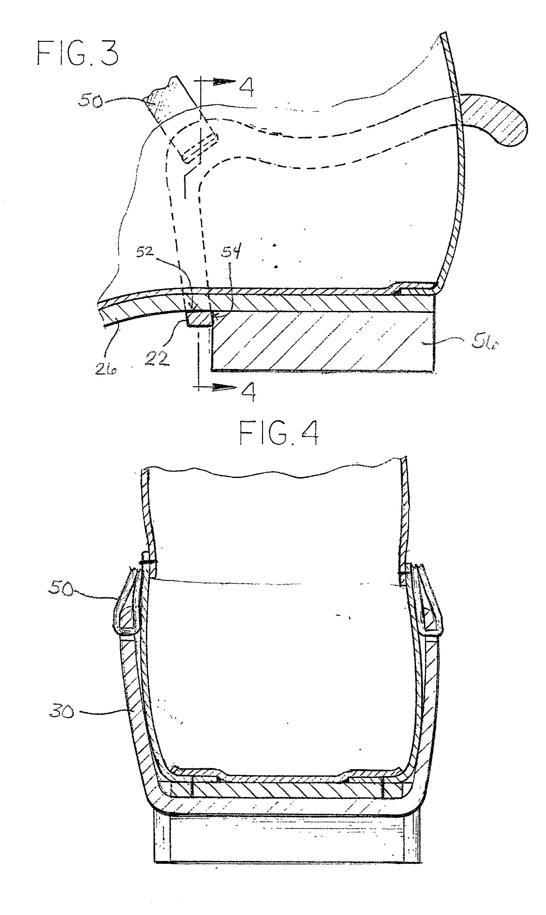
[0020] Briefly, and in accordance with the foregoing, the present invention discloses an ergonomic spur which is designed for use with a riding boot. The spur can be removably attached to the riding boot without damaging the riding boot. The spur can be used with a riding boot which does not have a groove between the boot's upper and the sole of the boot. The arch brace of the spur of the present invention provides two planes of contact between the spur and the riding boot. The spur of the present invention works ergonomically to precisely translate the rider's directions to the horse. In addition to providing a spur with increased stability, the spur of the present invention is dimensioned to have an appearance which is suitable for English-style riding.

Problems solved by technology

One disadvantage presented by the spur in the Beaston '958 patent is that it can only be used with a boot which has a groove between the sole and the boot upper.
The result is that the spur is relatively large and bulky in appearance.
Western-style riding equipment is generally bulkier than English-style riding equipment.
Because of the desire to create an elegant appearance, the bulky Dean spur is not acceptable for English-style riding.
The width of the Dean spur does not blend with the overall appearance of English-style riding equipment.
However, if the Dean spur were to be worn with an English-style riding boot the arch brace would only contact the sole of the boot at the rearward edge of the arch brace.
Because minimal contact is made between the sole of the boot and the arch brace, stability is lost.
When the spur is used by the rider, this lack of stability causes the spur to wobble.
Therefore, there is essentially only one plane of contact between the arch brace and the boot and, as a result, the spur is likely to be relatively unstable.

Method used


Image

  • Ergonomic spur
  • Ergonomic spur
  • Ergonomic spur

Examples


Embodiment Construction

[0026] While the invention may be susceptible to embodiment in different forms, there is shown in the drawings, and herein will be described in detail, specific embodiments with the understanding that the present disclosure is to be considered an exemplification of the principles of the invention, and is not intended to limit the invention to that as illustrated and described herein.

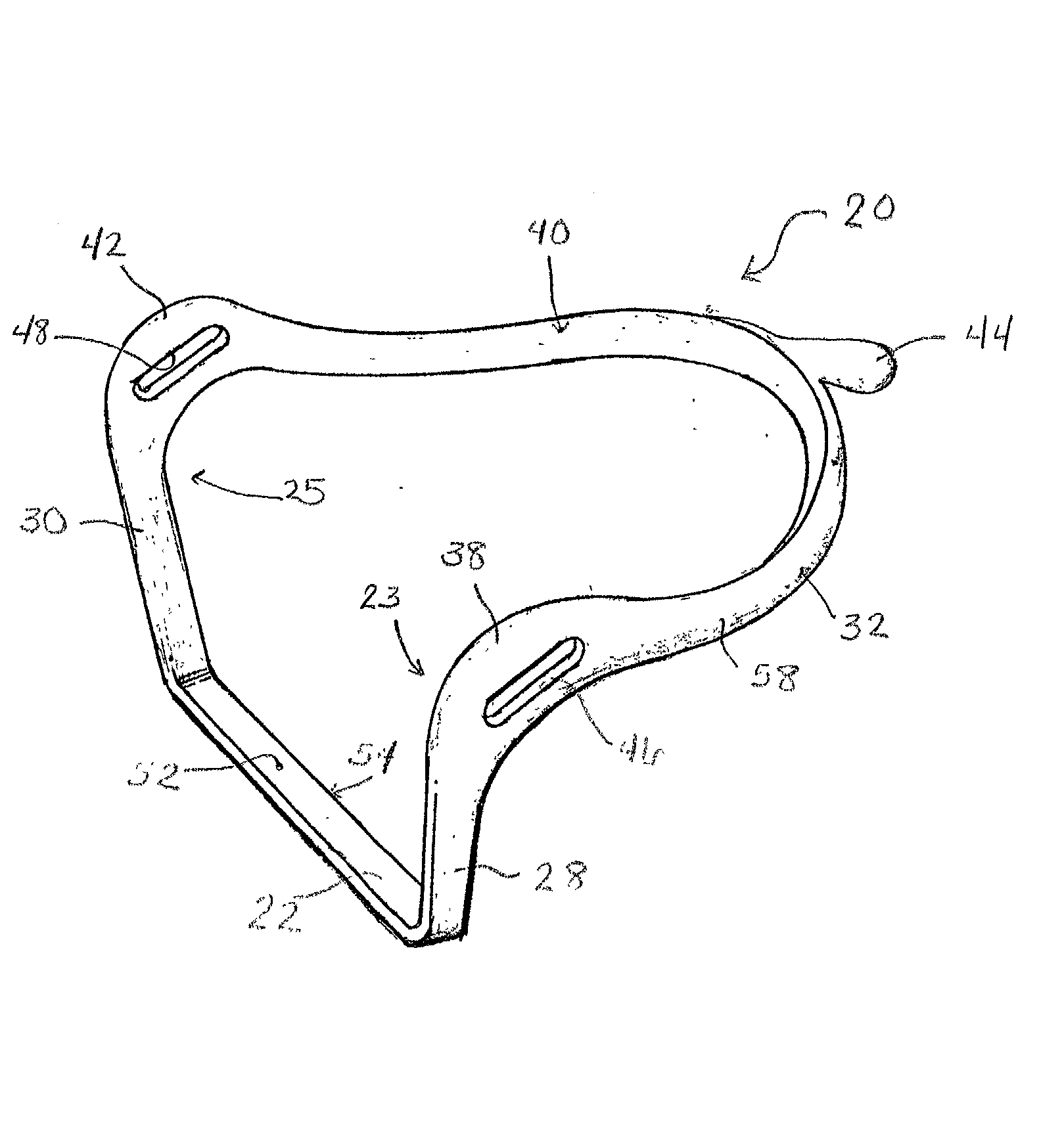
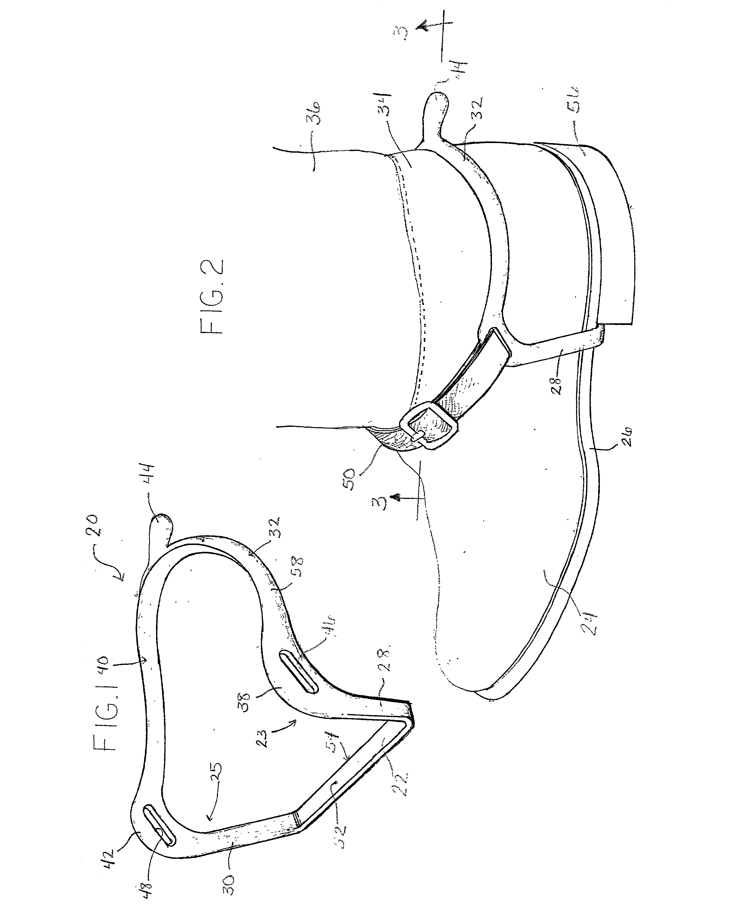
[0027] The invention is an ergonomic spur to be used when riding a horse. FIG. 1 shows a perspective view of an embodiment of the spur 20 and FIG. 2 illustrates the manner in which the spur 20 may be worn. The spur 20 is rigid and is preferably constructed from stainless steel as a single integrally formed piece.

[0028] The spur 20 includes an arch brace or under strap 22, molded directly into the design. When the spur 20 is worn over a boot 24 as shown in FIG. 2, the arch brace 22 is placed against the sole 26 of the boot 24. The arch brace 22 extends horizontally across the width of the boot. Two suppor...


PUM


Abstract

The present invention is an ergonomic spur which is designed for engagement with a riding boot. The spur can be removably attached to the riding boot with out damaging the boot. The arch brace of the spur of the present invention provides two planes of contact between the spur and the riding boot. The spur is formed in a manner which allows for sufficient rigidity without covering a large potion of the boot's surface area.

Description

BACKGROUND OF THE INVENTTON[0001] This invention is generally directed to an ergonomic spur. More particularly the invention relates to an ergonomic spur designed to be secured to an English style riding boot.[0002] Generally speaking, a spur is a protrusion which extends from the heel portion of a boot. When used for riding a horse the spur is used to direct or control the horse's movements or direction. Spurs have also been used in an ornamental manner. Ornamentally, spurs have been worn as portions of dance costumes and have been worn by soliders to indicate their rank.[0003] Spurs which have a decorative purpose are generally removably attached to the boot and are designed to provide little or no rigidity. These type of spurs are designed to bend or give way when they come into contact with another object because they are sometimes used when dancing amongst groups of people. In the interest of safety, it is important that the spur give way when it makes contact with another obje...

Claims


Application Information

Patent Timeline
IPC IPC(8): A43B17/02
CPCA43C17/02A43C17/04
Inventor MARTIN, BRIAN V.
Owner LIBERTYVILLE SADDLE SHOP
Learn More