Exhaust control device and method for manufacture thereof

a technology of exhaust control device and exhaust gas, which is applied in the direction of machine/engine, separation process, physical/chemical process catalyst, etc., can solve the problem of significant process loss

Inactive Publication Date: 2002-09-12
DELPHI TECH INC
View PDF0 Cites 69 Cited by
  • Summary
  • Abstract
  • Description
  • Claims
  • Application Information

AI Technical Summary

Benefits of technology

0007] Disclosed herein is an exhaust emissions control device and method for making the same. The method for manufacturing the exhaust emission control device comprises: disposing a mat suppo

Problems solved by technology

If the current art of manufacturing exhaust emission control devices is used with these fragile substrates, there will be s

Method used


Image

  • Exhaust control device and method for manufacture thereof
  • Exhaust control device and method for manufacture thereof
  • Exhaust control device and method for manufacture thereof

Examples


Embodiment Construction

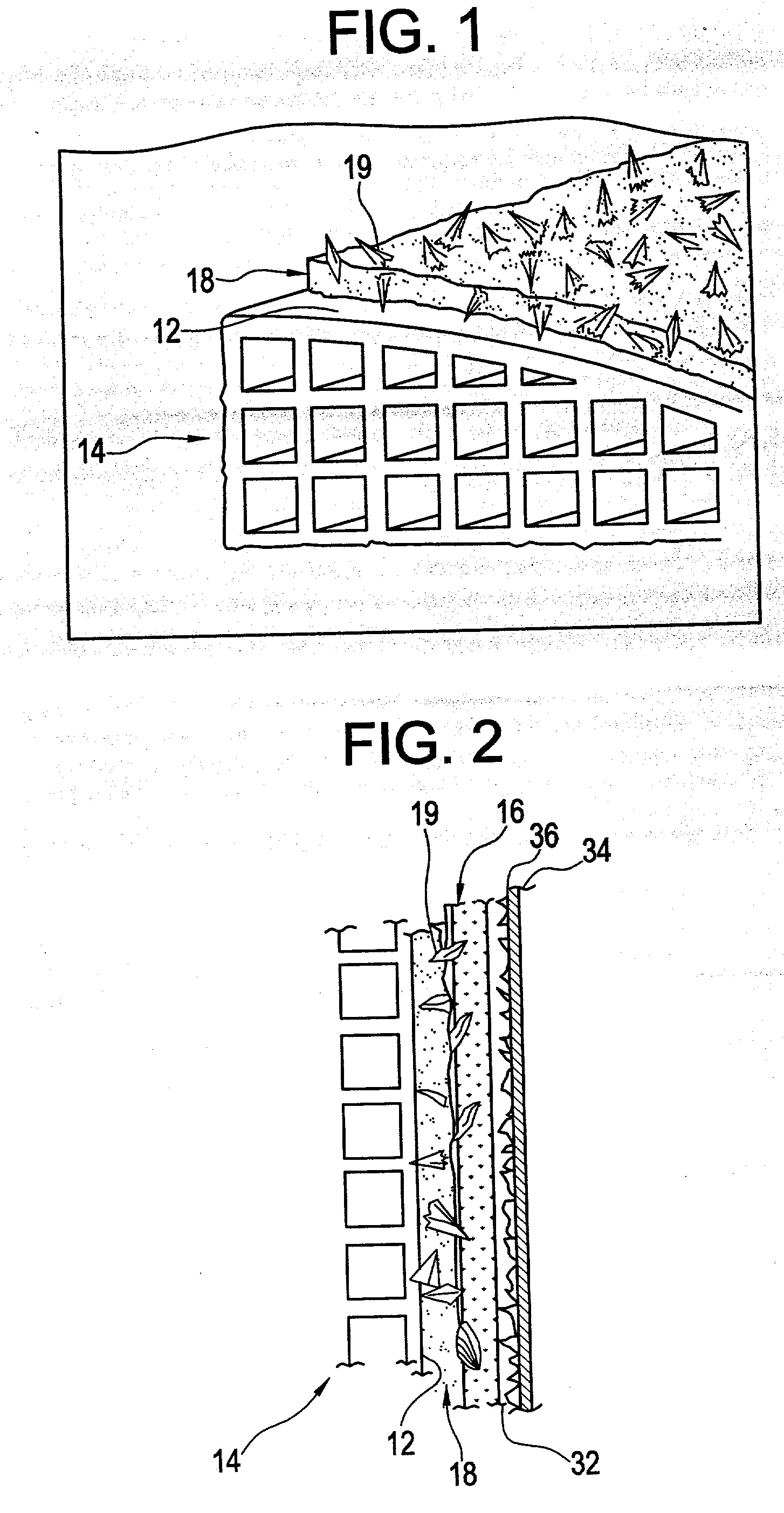
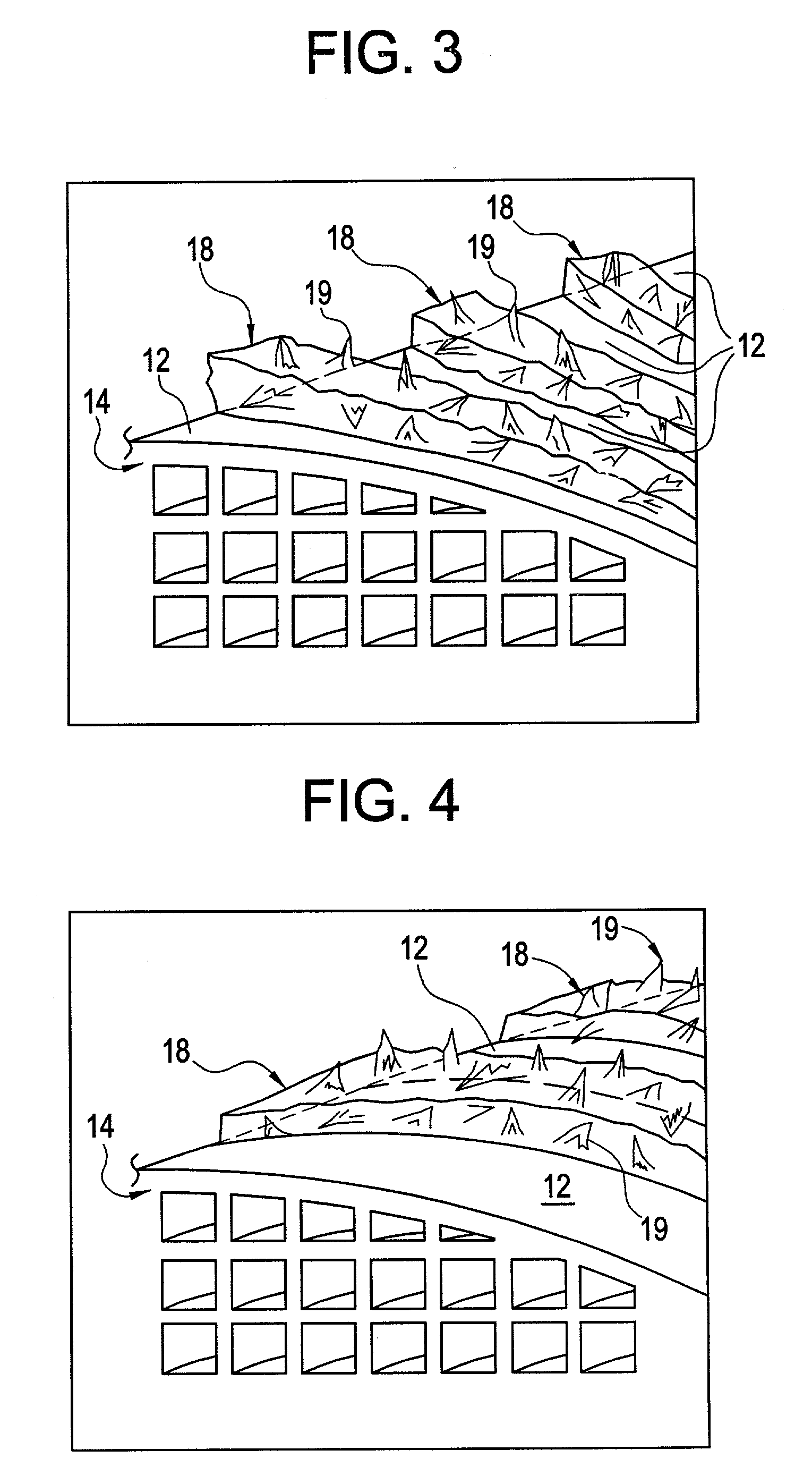
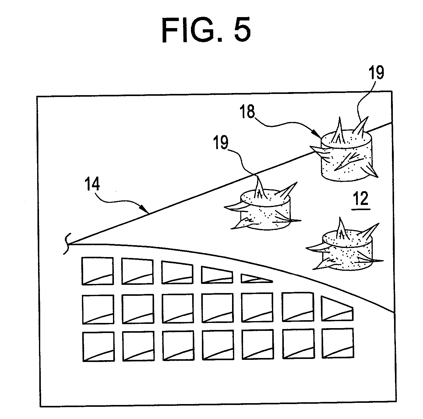
[0023] As used herein, a roughened surface means a surface where the "vertical" variation to a uniform surface includes a distance of greater than or equal about 0.1 millimeters (mm), with greater than or equal to about 0.3 mm preferred. Also preferred is a vertical variation of less than or equal to about 3.0 mm, with less than or equal to about 1.0 mm more preferred. The shape of the non-uniform surface preferably comprises rapid surface changes, i.e., a change in distance to a uniform surface of greater than or equal to about 50% of the vertical variation within 50% of the vertical height (e.g., the angle from each peak should average greater than or equal to about 45 degrees). The distance between irregularities can be about 0.1 mm to about 10.0 mm with a distance of about 0.5 mm to about 5.0 mm preferred.

[0024] The long-term durability of the exhaust emission control device is predicated upon the retention of the substrate. Presently, retention of the fragile substrate is achie...


PUM

PropertyMeasurementUnit
Velocityaaaaaaaaaa
Frictionaaaaaaaaaa

Abstract

Disclosed herein is an exhaust emissions control device and method for making the same. The method for manufacturing the exhaust emission control device comprises: disposing a mat support and a substrate in a shell, wherein the mat support is disposed between the substrate and the shell, and wherein the shell has a roughened surface in physical contact with the mat support. In one embodiment, the exhaust emissions control device comprises: a shell, a substrate disposed within the shell, and a mat support disposed between the substrate and the shell, wherein the shell has a roughened inner surface in physical contact with the mat support.

Description

CROSS REFERENCE TO RELATED APPLICATIONS[0001] The present application is a continuation-in-part application of U.S. patent application Ser. No. 09 / 518,573, filed Mar. 3, 2000, which is hereby incorporated by reference in its entirety.TECHNICAL FIELD[0002] The disclosure relates to emission control devices and, more particularly, to an apparatus and method for increasing the static coefficient of friction within an emission control device.BACKGROUND OF THE INVENTION[0003] The removal of emissions, such as hydrocarbon, carbon monoxide, nitrogen oxide, particulate matter, and the like, from the exhaust gases of internal combustion engines, in flue gases, and the like, is required to meet increasingly strict environmental standards. One focus area for such exhaust emission reduction has been in the area of post combustion treatment. Namely, post combustion treatment includes the placement of one or more exhaust emission control devices in the exhaust stream downstream of the internal co...

Claims


Application Information

Patent Timeline
IPC IPC(8): B01D53/88B01J35/04F01N3/28
CPCB01J35/04F01N3/2853F01N3/2864
Inventor FOSTER, MICHAEL R.JANKOWSKI, PAUL E.
Owner DELPHI TECH INC
Why Eureka
Try Eureka