

Tire machining tool
a technology of machining tools and machining parts, which is applied in the direction of manufacturing tools, shaping cutters, wood boring tools, etc., can solve problems such as superficial heating
- Summary
- Abstract
- Description
- Claims
- Application Information
AI Technical Summary
Problems solved by technology
Method used
Image

Examples
Embodiment Construction
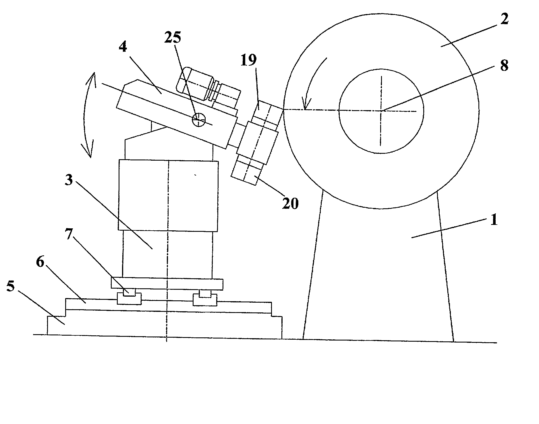
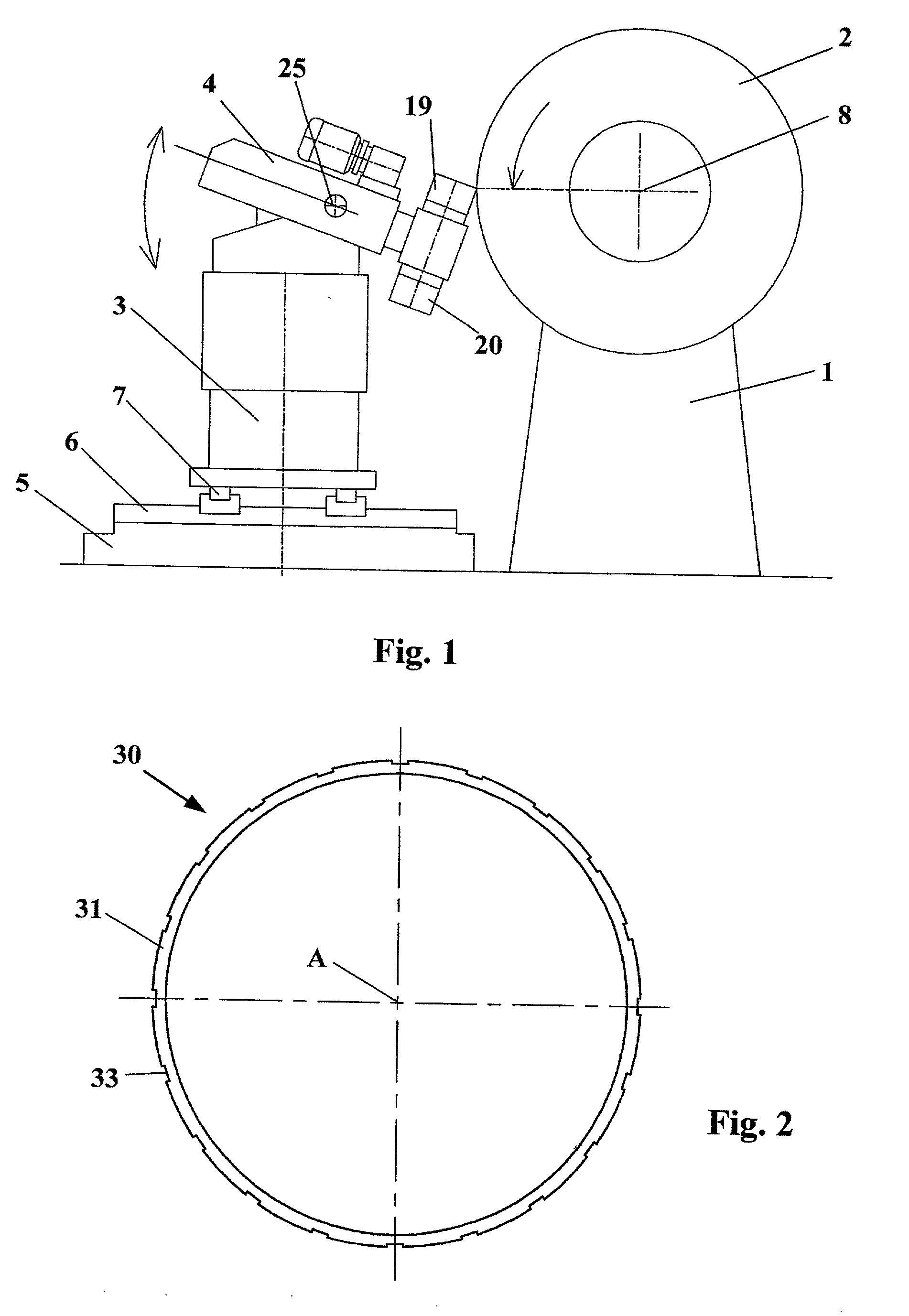
[0024] FIG. 1 is a highly schematic view of a machine for machining tire treads comprising a cutting tool according to the invention. The machine comprises a first fixed frame 1 supporting a drum (not shown) on which is mounted a tire 2. The machine also comprises a mobile frame 3 supporting a tool holder 4. The frame 3 is mounted on a fixed base 5 by means of two pairs of horizontal rails 6 and 7. The rails 6 are oriented perpendicularly to the axis of rotation 8 of the tire and permit translational movement of the frame 3 towards or away from the tire 2. The rails 7 are oriented parallel to the axis of rotation 8 of the tire and permit translational displacement of the frame 3 parallel to the axis of rotation of the tire 2. The combination of these two translational movement allows the cutting tool to follow all the conventional tire profiles. The frame 3 also allows vertical displacement of the tool holder 4, due to conventional means which are not shown. The machine additionally...
PUM
| Property | Measurement | Unit |
|---|---|---|
| angle | aaaaa | aaaaa |
| angle | aaaaa | aaaaa |
| angle | aaaaa | aaaaa |
Abstract
Description
Claims
Application Information