
Medical device for correcting finger joint contractures

a finger joint and medical device technology, applied in the field of finger joints, can solve the problems of muscle imbalance across joints, torque that these devices impose to increase the range of motion of joints, and the torque must be applied for a significant amount of tim

Inactive Publication Date: 2002-11-14
JOHN M AGEE & KAREN K AGEE TRUSTEES OF THE JOHN M AGEE TRUST
View PDF0 Cites 5 Cited by
  • Summary
  • Abstract
  • Description
  • Claims
  • Application Information

AI Technical Summary

Benefits of technology

[0017] One of the discoveries arising from this invention is that despite the shift of the pivot axis to a location away from the joint itself, an effective and controllable torque can be applied to the PIP joint as the joint rotates. Another discovery is that when the pivot axis and the torque-producing element are positioned such that the length of the moment arm varies in inverse relation to the force applied to the torque-producing element (i.e., the moment arm lengthens as the torque-producing element is relaxed), the relative positions of the pivot axis and torque-producing element can be adjusted to produce a torque that remains relatively steady as the joint flexes. A further discovery and advantage of the invention are the ability of the device to impose a torque on the PIP joint without imposing a functionally significant torque on any of the neighboring joints, including the metacarpal phalangeal (MP) joint on the same finger. Still further discoveries and advantages will be apparent from the description that follows.
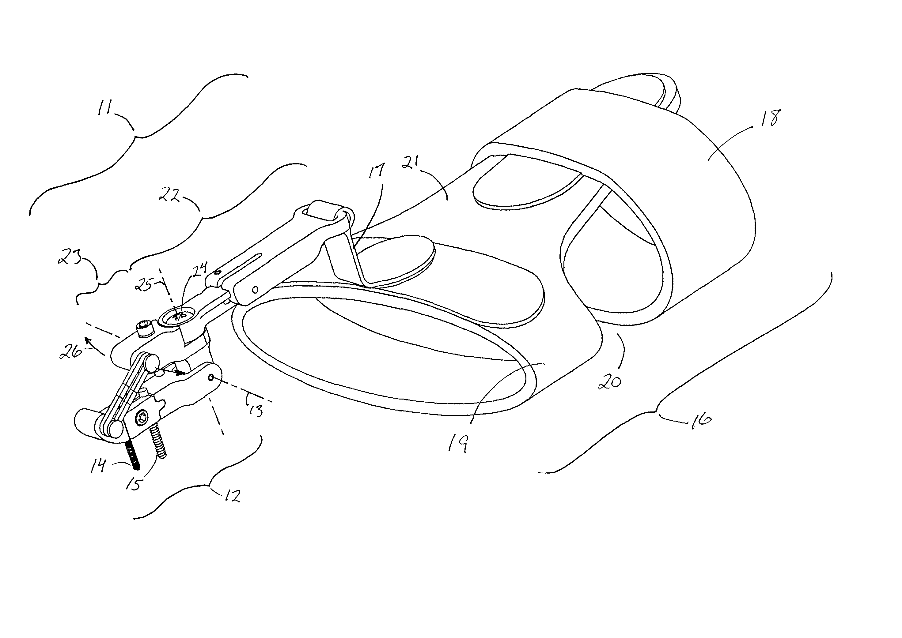
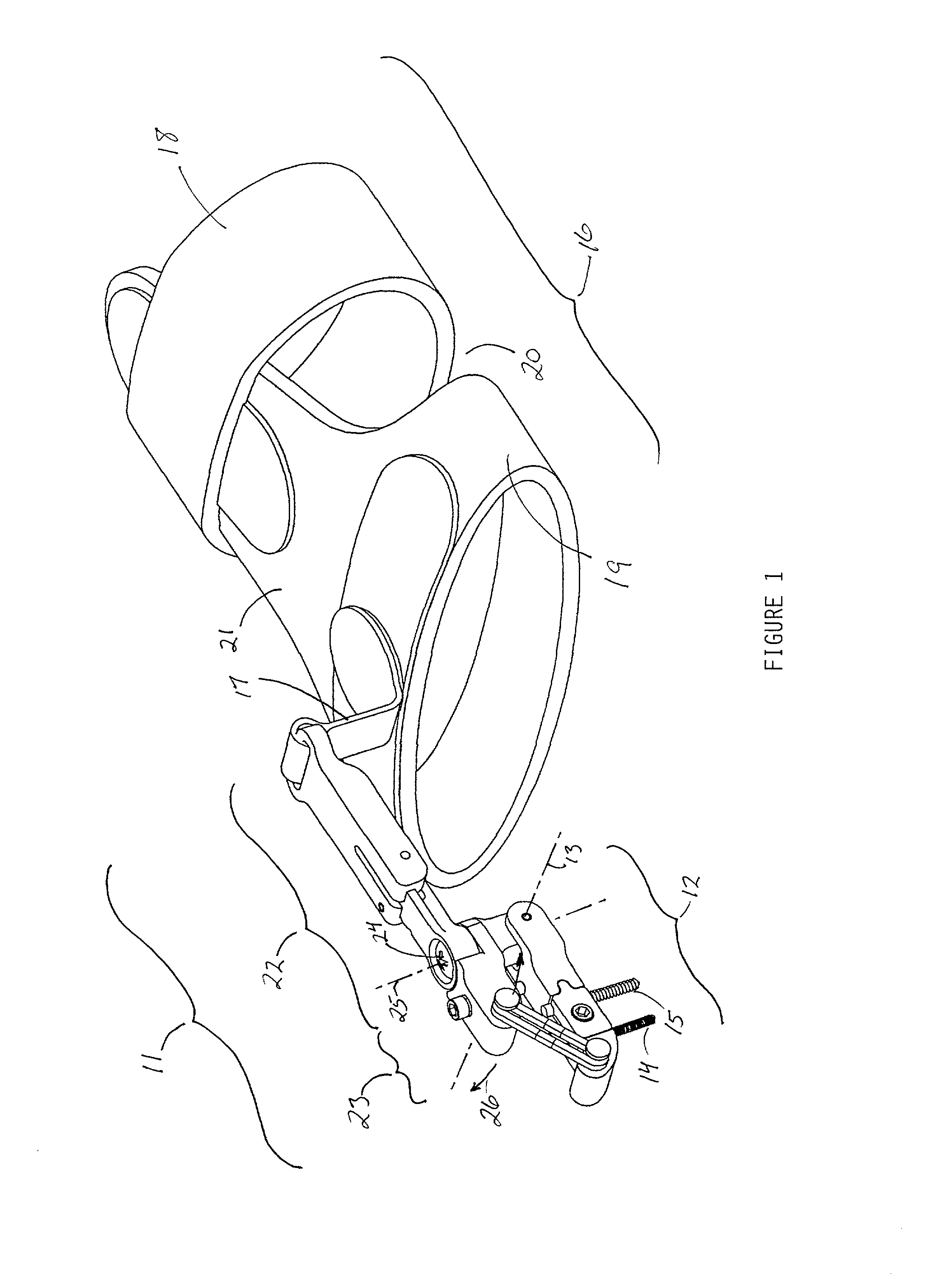
[0018] FIG. 1 is a perspective view of one example of a PIP joint contracture treatment device in accordance with this invention.
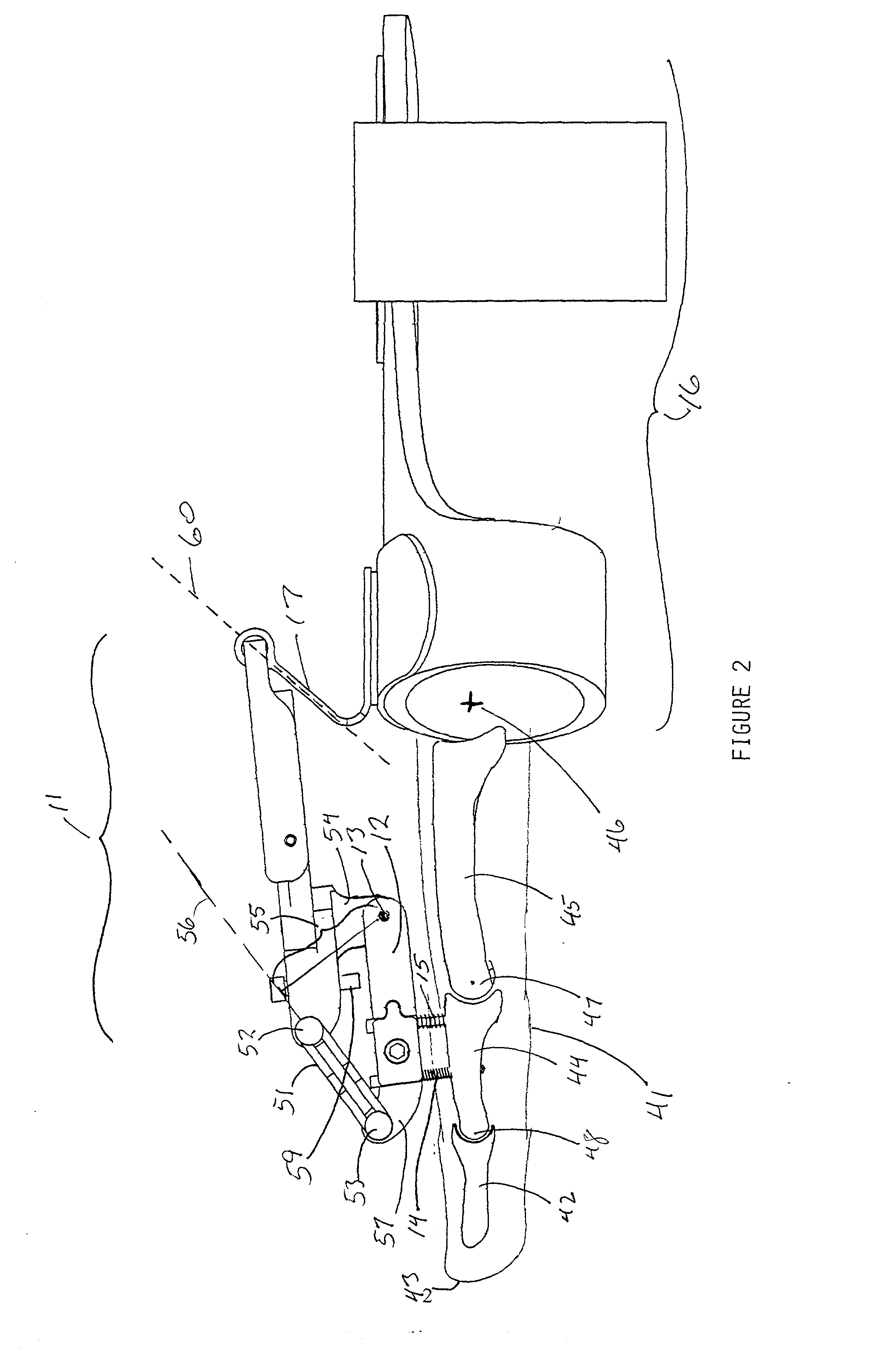
[0019] FIG. 2 is a side elevation view of the device of FIG. 1, shown installed on a patient's finger with the finger in its fully extended position.
[0020] FIG. 3 is a view similar to that of FIG. 2 except that the finger is shown in a partially flexed position.
[0021] FIG. 4 is a view similar to that of FIG. 2 except that the finger is shown in a fully flexed position.
[0022] FIG. 5a is a bottom view of a portion of the proximal support beam of the device shown in the preceding figures. FIG. 5b is a side elevation of the same portion.

Problems solved by technology

Contractures also result from muscle imbalance across joints and often accompany diseases such as leprosy and Dupuytren's disease.
A disadvantage of some prior art devices is that the torque that these devices impose to increase the range of motion of the joint is applied through the skin overlying the skeletal segments extending from one or both sides of the joint.
An aggravating factor is that the torque must be applied for a significant amount of time before it will successfully increase the range of motion of the joint.
If the torque is transmitted to the skeleton indirectly through the skin, the force applied to the skin compromises circulation under the contact site and causes the skin to become tender, red and inflamed.
In severe cases, particularly those with compromised sensation, ulcers may develop.
While the Hotchkiss et al. device, the Messina et al. device, and similar devices have achieved success, these devices have certain limitations.
Because of the laterally extending pins on these devices and the external elements attached to these pins, these devices are difficult to use on the middle and ring fingers and are instead more useful for joints on the border (index and little) fingers.
A further difficulty is that installation of these devices on the PIP joints of the long or ring fingers necessitates partial spreading of the adjacent fingers, and the spread position must be maintained throughout the treatment period.
In general, a Hotchkiss- or Messina-type device on one finger tends to interfere with the use and movement of adjacent fingers and the use of the hand, especially the palmar surface of the hand, for pinching and grasping.

Method used


Image

  • Medical device for correcting finger joint contractures
  • Medical device for correcting finger joint contractures
  • Medical device for correcting finger joint contractures

Examples


Embodiment Construction

[0026] While the features and principles that characterize this invention and distinguish it over the prior art may be implemented in a variety of ways and embodied in a variety of constructions, these features and principles can best be understood by examination of specific examples. Several such examples are depicted in the attached figures.

[0027] FIG. 1 is a perspective view from above of a device illustrating an embodiment of the invention that is designed for the correction of a contracture or of a limited range of flexion. The two pivotally joined sections are a proximal support beam 11 and a distal support beam 12, each of which is elongate in shape and primarily straight, and the pivot axis 11 along which these beams are joined is perpendicular to each of the two beams. Attachment of the device to the patient's hand and finger is achieved by a pair of pins 14, 15 extending from the underside of the distal support beam 12 for securement to the middle phalanx through the dorsa...


PUM


Abstract

A finger suffering from contracture of the proximal interphalangeal (PIP) joint is treated by application of a device that includes two pivotally joined sections, one of which is securable to the middle phalanx of the finger and the other to another portion of the patient's finger, hand or wrist, with an element that applies torque to the sections. The pivot axis of the two sections is dorsal to the finger, and the torque-producing element and the pivot axis define a moment arm whose length varies in inverse relation to the tension applied to the tensioning element. Torque is applied to the PIP joint without a functionally significant torque being applied to the metacarpal phalangeal (MP) joint, and the device requires attachment only to the dorsal aspect of the phalanx that is distal to the joint being treated rather than to both the distal phalanx and the proximal phalanx.

Description

[0001] 1. Field of the Invention[0002] This invention addresses injuries and disorders of the musculoskeletal system in general and finger joints in particular, and relates to medical and surgical methods and devices for the correction of these conditions. More particularly this invention provides dynamic orthopedic methods and devices that increase the range of motion of finger joints suffering from contractures.[0003] 2. Description of the Prior Art[0004] Skeletal joint contractures (also known as flexion contractures), including fractures and dislocations of joints which reduce the range of motion of the joints, may result from trauma or from bums and the scars left after bums heal. Contractures also result from muscle imbalance across joints and often accompany diseases such as leprosy and Dupuytren's disease. Dupuytren's disease, for example, commonly causes flexion contractures of the small joints of the hand. Any skeletal joint may be subject to disorders or abnormalities of ...

Claims


Application Information

Patent Timeline
Patent Type & Authority Applications(United States)
IPC IPC(8): A61B17/64
CPCA61B17/6425
Inventor AGEE, JOHN M.WOODHOUSE, JEFFREY
Owner JOHN M AGEE & KAREN K AGEE TRUSTEES OF THE JOHN M AGEE TRUST
Learn More