Vessel occlusion clamp

a technology of occlusion clamp and blood vessel, which is applied in the field of surgical clamps, can solve the problems of reducing the bendibility or flexibility of the jaws

Inactive Publication Date: 2002-12-05
APPL MEDICAL RESOURCES CORP
View PDF8 Cites 15 Cited by
  • Summary
  • Abstract
  • Description
  • Claims
  • Application Information

AI Technical Summary

Problems solved by technology

In a preferred embodiment of the clamp, the jaws are provided with a receding or tapered T-beam cross section, which greatly reduces the bendibility or flexibility of the jaws.

Method used


Image

  • Vessel occlusion clamp
  • Vessel occlusion clamp
  • Vessel occlusion clamp

Examples


Embodiment Construction

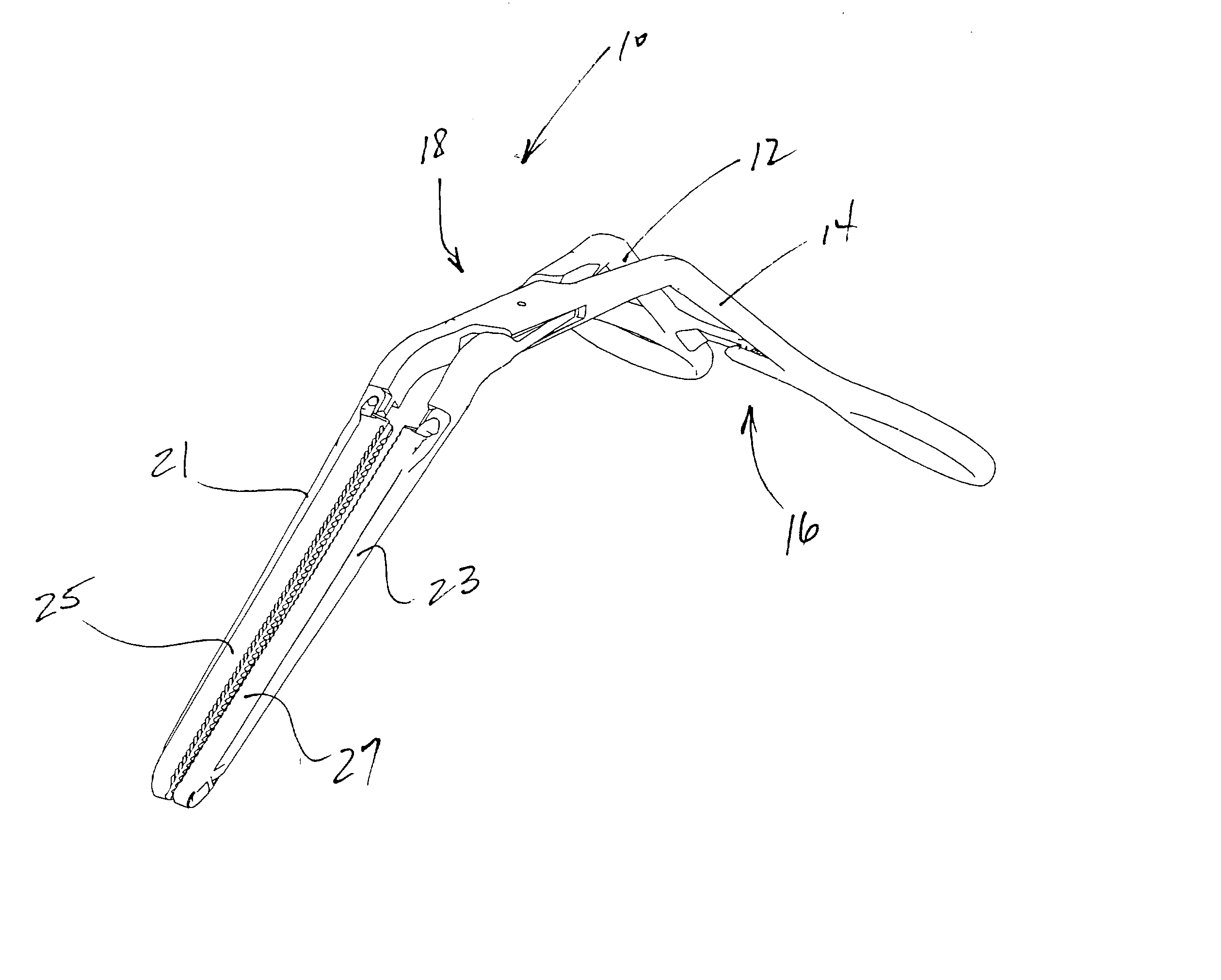
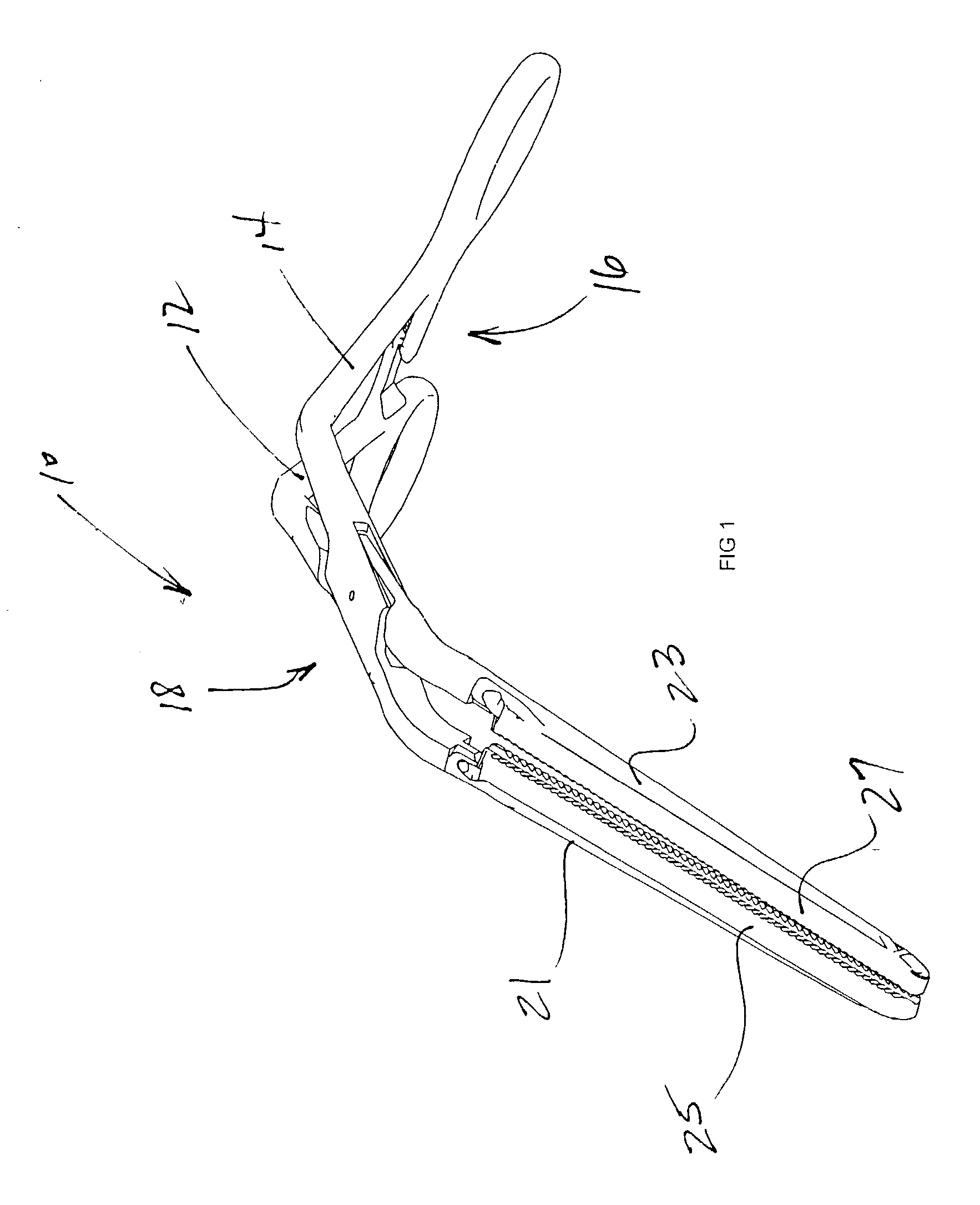
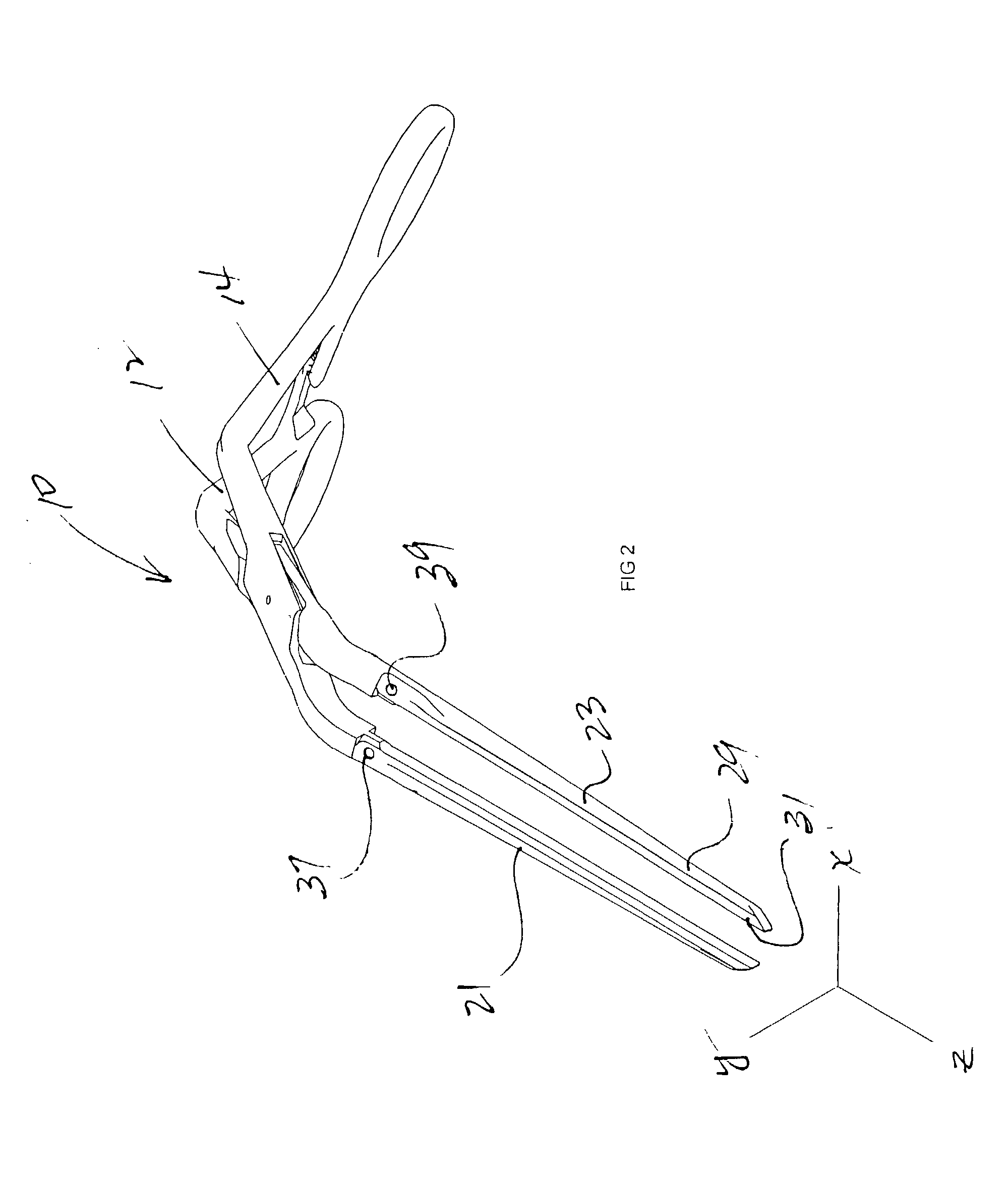
[0020] A vascular occlusion clamp of the Bahnson type is illustrated in FIG. 1 and designated generally by the referenced numeral 10. The clamp 10 includes a pair of handles 12 and 14 with a ratchet lock 16, which pivot on a fulcrum 18 to move jaws 21 and 23 in a generally parallel relationship. Disposable inserts 25 and 27 are removably mounted on the associated jaws 21, 23. In FIG. 2, the inserts 25 and 27 have been removed in order to illustrate the dimensional-shaped design of the jaws 21 and 23. From this view it can be seen that the jaws 21 and 23 extend along a Z axis but move generally along an X axis. The width of the jaws is measured along a Y axis. Thus the jaws having a length along the Z axis, a width along the Y axis, and a thickness along the X axis.

[0021] This dimensional-shaped design is further illustrated in the side-elevation view of FIG. 3 and the associated cross sectional views of FIGS. 4 and 5. The side elevation view of FIG. 3 is drawn in the YZ plane while ...


PUM


Abstract

A surgical clamp for occluding a body conduit includes first and second jaws moveable relative to each other in a generally parallel relationship. A handle assembly is operable to move the jaws relative to each other between a space position and proximate position. The first jaw has an elongate configuration characterized by a length and a width. First portions of the first jaw have in cross section a first shape which remains generally constant in area along the first jaw, while second portions have in cross section a second shape which varies in area along the length of the first jaw. The resulting clamp has a low profile jaw design which dimensional-shaped cross section which provide increased stiffness and reduced flexibility.

Description

[0001] 1. Field of the Invention[0002] This invention relates generally to surgical clamps, and more specifically to blood vessel occlusion clamps.[0003] 2. Discussion of the Prior Art[0004] Surgical occlusion clamps are commonly used to close off or occlude body conduits, such as blood vessels. A common variety of vessel occlusion clamp is that referred to as a "Bahnson" clamp, which has small metal handles that operate a pair of opposing jaws. When the jaws are brought into close proximity on either side of a vessel, the vessel is squeezed against itself to achieve at least partial occlusion. It is of particular importance that the jaws of the clamp be stable, and sufficiently inflexible that the jaws do not cross over or scissor, but rather press directly against each other along their length to occlude any conduit disposed between the jaws.[0005] It is also desirable to have a thin, low-profile jaw design that can access narrow areas. In the past, this desire for a low-profile d...

Claims


Application Information

Patent Timeline
Patent Type & Authority Applications(United States)
IPC IPC(8): A61B17/122A61B17/12A61B17/28
CPCA61B17/122A61B2017/2825A61B2017/2808A61B17/282
Inventor ANDERSON, STEVEN R.
Owner APPL MEDICAL RESOURCES CORP
Why Eureka
Try Eureka