
Image coding method and apparatus and image decoding method and apparatus

a technology of image coding and decoding, applied in the field of image processing technology, can solve the problems of preventing the compression rate from being improved, hard to predict the evolution of digital culture, and degrading image quality

Inactive Publication Date: 2002-12-19
JBF PARTNERS
View PDF10 Cites 83 Cited by
  • Summary
  • Abstract
  • Description
  • Claims
  • Application Information

AI Technical Summary

Benefits of technology

0064] First, the multiresolutional critical point filter technology and the image matching processing using the technology, both of which will be utilized in the preferred embodiments, will be described in detail as "Base Technology". Namely, the following sections [1] and [2] (below) belong to the base technology, where section [1] describes elemental techniques and section [2] describes a processing procedure. These techniques are patented under Japanese Patent No. 2927350 and owned by the same assignee of the present invention. However, it is to be noted that the image matching techniques provided in the present embodiments are not limited to the same levels. In particular, in FIGS. 18 to 25, image data coding and decoding techniques, utilizing, in part, the base technology, will be described in more detail.

Problems solved by technology

Thus, we are facing a situation where it is hard to predict how the digital culture would evolve in this age of broadband.
It is a well-known fact that block distortion in MPEG compression is sometimes responsible for causing degraded image quality and preventing the compression rate from being improved.
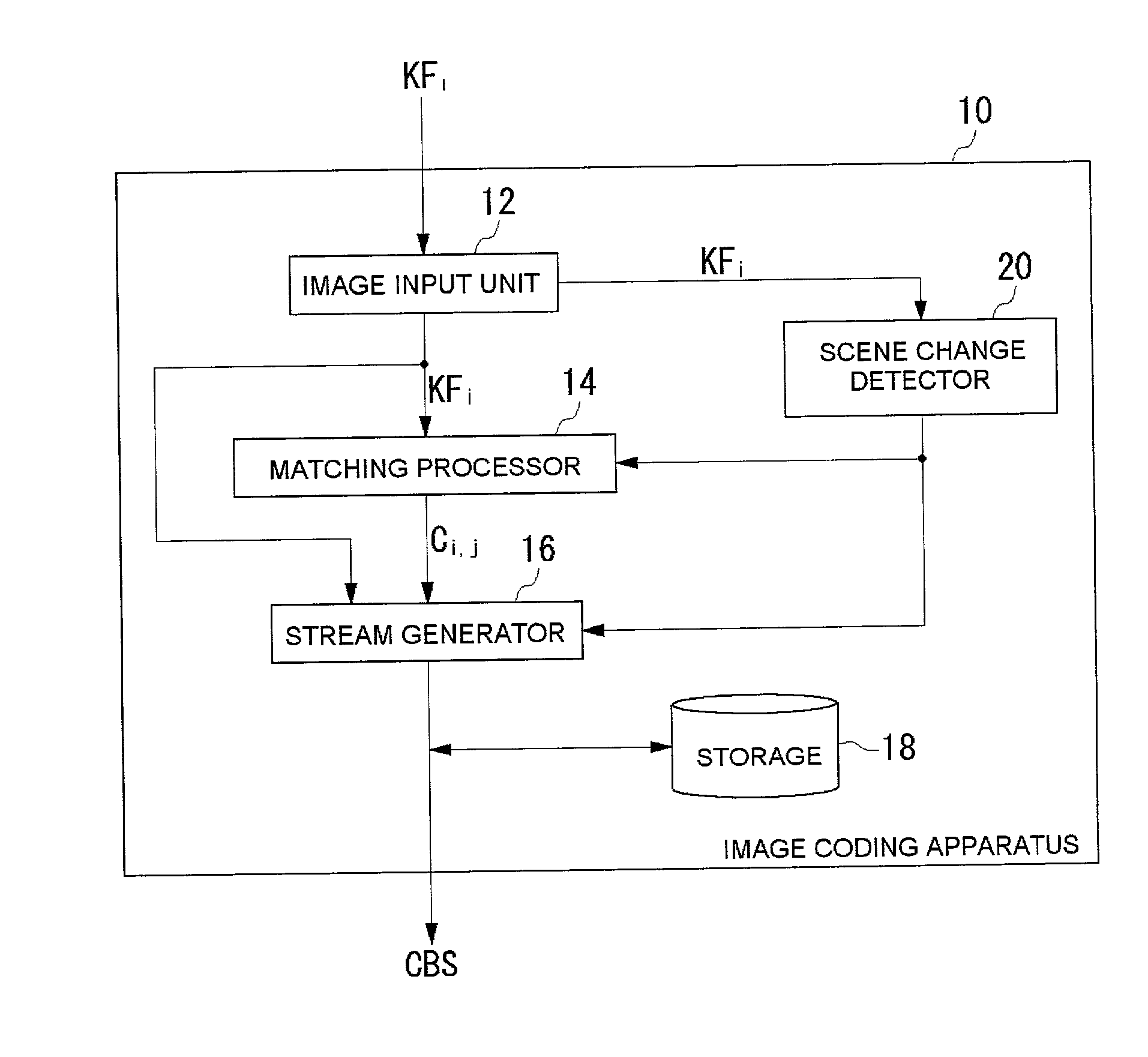
Further, the term "scene change" is not necessarily determined objectively, and it may be considered that there is a scene change in a case when there exists a predetermined difference, for example, a certain degree of difference, between images.

Method used


Image

  • Image coding method and apparatus and image decoding method and apparatus
  • Image coding method and apparatus and image decoding method and apparatus
  • Image coding method and apparatus and image decoding method and apparatus

Examples


Embodiment Construction

of Elemental Techniques

[1.1] Introduction

[0065] Using a set of new multiresolutional filters called critical point filters, image matching is accurately computed There is no need for any prior knowledge concerning the content of the images or objects in question. The matching of the images is computed at each resolution while proceeding through the resolution hierarchy. The resolution hierarchy proceeds from a coarse level to a fine level. Parameters necessary for the computation are set completely automatically by dynamical computation analogous to human visual systems. Thus, There is no need to manually specify the correspondence of points between the images.

[0066] The base technology can be applied to, for instance, completely automated morphing, object recognition, stereo photogrammetry, volume rendering, and smooth generation of motion images from a small number of frames. When applied to morphing, given images can be automatically transformed. When applied to volume rendering,...


PUM


Abstract

An image coding and decoding technology for compressing motion pictures which makes use of critical point filter technology and that includes detection of scene changes to provide more accurate decoding. An image input unit acquires key frames. A scene change detector detects when there is a scene change between key frames, and notifies a matching processor to that effect. The matching processor then skips generation of correspondence data between those key frames. A stream generator generates a coded data stream in a manner that key frames and associated correspondence data are incorporated when there is no scene change, while key frames and associated correspondence disable data are incorporated when there is a scene change. This allows a decoder to more accurately decode the data stream and take account of scene changes.

Description

[0001] 1. Field of the Invention[0002] The present invention relates to an image processing technology, and more particularly relates to a method and apparatus for coding and decoding images, with an emphasis on compression of moving pictures.[0003] 2. Description of the Related Art[0004] Recently, image processing and compression methods such as those proposed by MPEG (Motion Picture Expert Group) have expanded to be used with transmission media such as network and broadcast rather than just storage media such as CDs. Generally speaking, the success of the digitization of broadcast materials has been caused at least in part by the availability of MPEG compression coding technology. In this way, a barrier that previously existed between broadcast and other types of communication has begun to disappear, leading to a diversification of service-providing businesses. Thus, we are facing a situation where it is hard to predict how the digital culture would evolve in this age of broadband...

Claims


Application Information

Patent Timeline
Patent Type & Authority Applications(United States)
IPC IPC(8): H04N5/14H04N19/50H04N19/20H04N19/30H04N19/46H04N19/587H04N19/70H04N19/87
CPCH04N5/147H04N19/142H04N19/87H04N19/537H04N19/179
Inventor AKIYOSHI, KOZOAKIYOSHI, NOBUO
Owner JBF PARTNERS
Learn More