Easy open envelope

Inactive Publication Date: 2003-01-23
ENVELOPE PROD GROUP
View PDF5 Cites 19 Cited by
  • Summary
  • Abstract
  • Description
  • Claims
  • Application Information

AI Technical Summary

Benefits of technology

[0010] Preferably, the tape strip is applied along one side of the front panel of an envelope blank, which has been scored and so divided into a front panel, rear panel, seal flap and side panels. The length of the tape strip may be extended beyond the length of the front panel and along the length of a corresponding region of the seal flap. Typically, before application of the tape strip to the seal flap, a gummy adhesive is applied to form a seal zone which, when adhered to the outside of the rear panel, forms the envelope closure. The tape strip may or may not overlap the seal zone, depending on the design and configuration of the seal flap. After the tape strip is applied to the blank, the corners of the seal flap are tapered by trimming the ends of the corners in an angular or curved fashion. This trimming step cuts through the excess paper substrate as well as the length of tape strip affixed to the excess substrate, and provides an identical cut line over the substrate material of the seal flap as well as the tape. After trimming, the upper free edge of the tape strip is contiguous with and symmetrically aligned to the upper free edge of the corresponding corner of the seal flap. A perforation may then be made along the region of tape affixed to the seal flap. The perforation may partially extend along the length of the tape strip, or it may extend along the entire length of the tape strip. In practice, the perforation permits the end of the tape, which is not itself covered by the gummy adhesive on the seal flap, to be lifted and torn away from the envelope body. The end of the tape strip thus forms a rip tab that allows easy initiation of the tearing action. In this respect, the seal flap and the attached rip tab so formed can be run through a stamp cancellation machine without being snagged or torn away by the equipment. An additional perforation may be included at or near the bottom of the front panel, to improve the tearing performance of the tape strip. This lower perforation may be angled between the side and lower edges of the front panel. The presence of both perforations, on the seal flap and on the lower front panel, allows the tape strip to be more precisely torn away from the envelope body such that the tear line is kept at or close to the edge of the tape strip itself.

Problems solved by technology

This prior art, while recognizing the need for an envelope that can be torn open without detriment to the contents, has not solved the problem of providing an envelope with a reliable tear mechanism that can readily be identified by the user, and which is easy to manufacture on-line in a machine process for making envelopes.

Method used


Image

  • Easy open envelope
  • Easy open envelope
  • Easy open envelope

Examples


Embodiment Construction

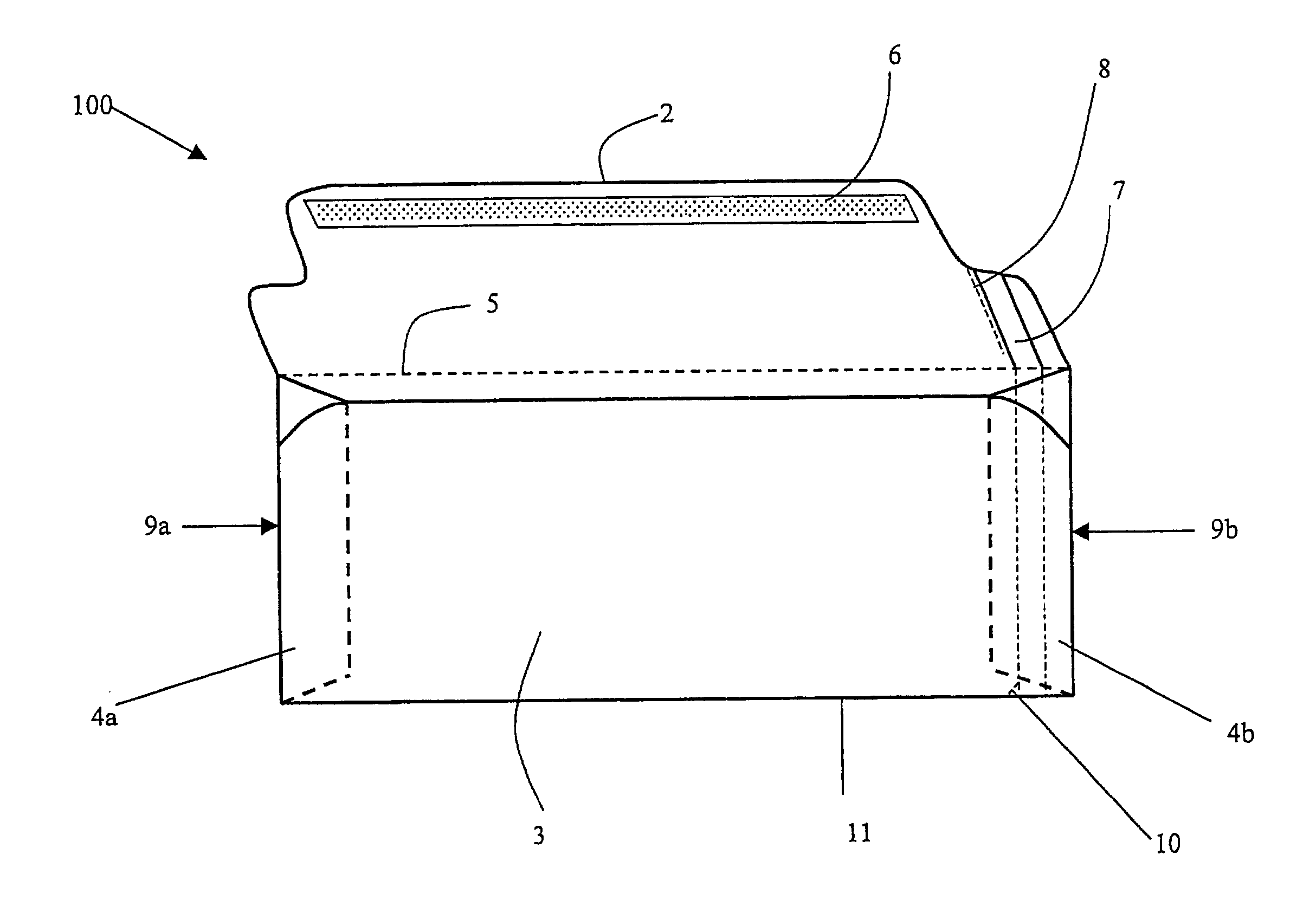
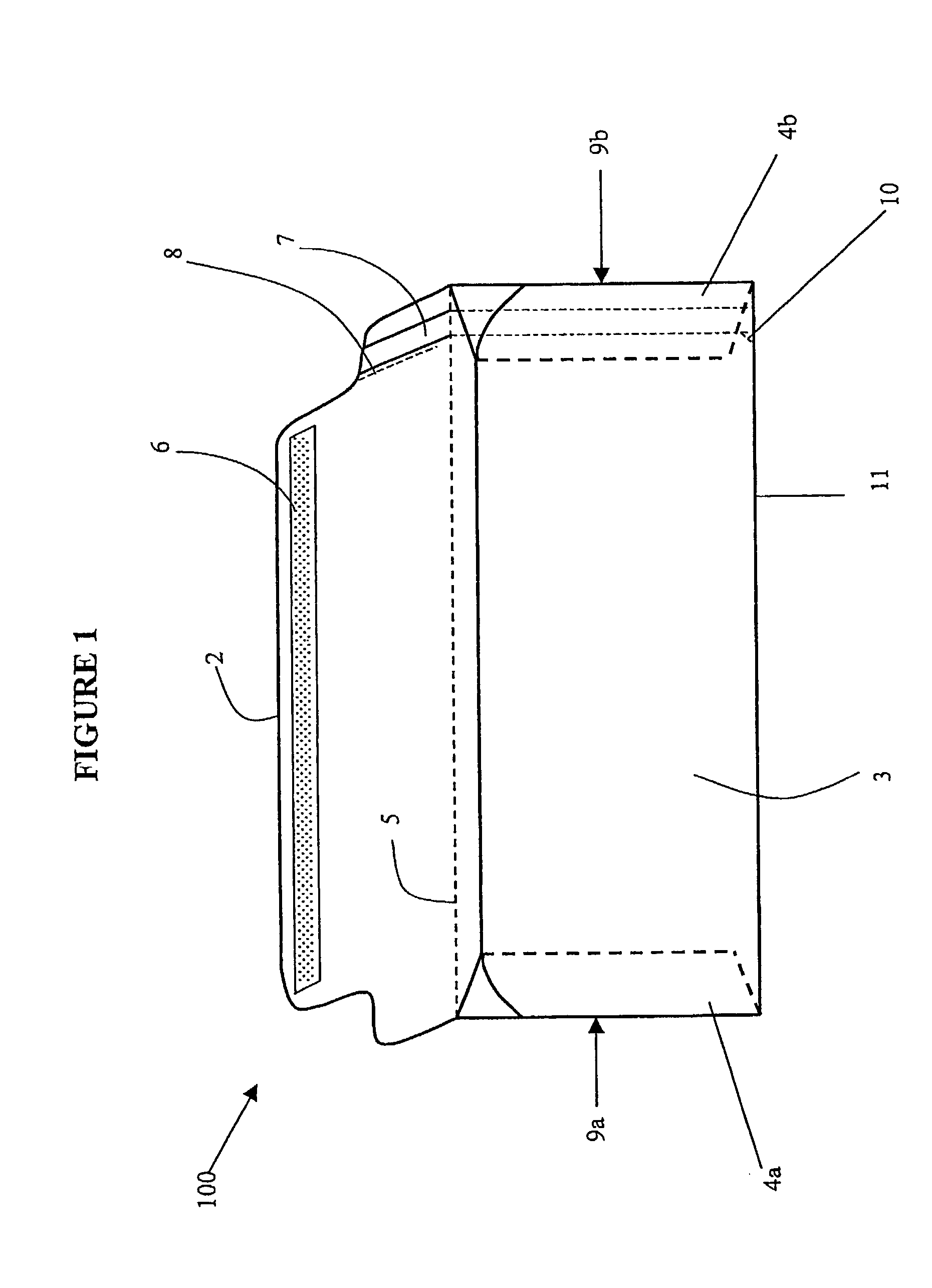
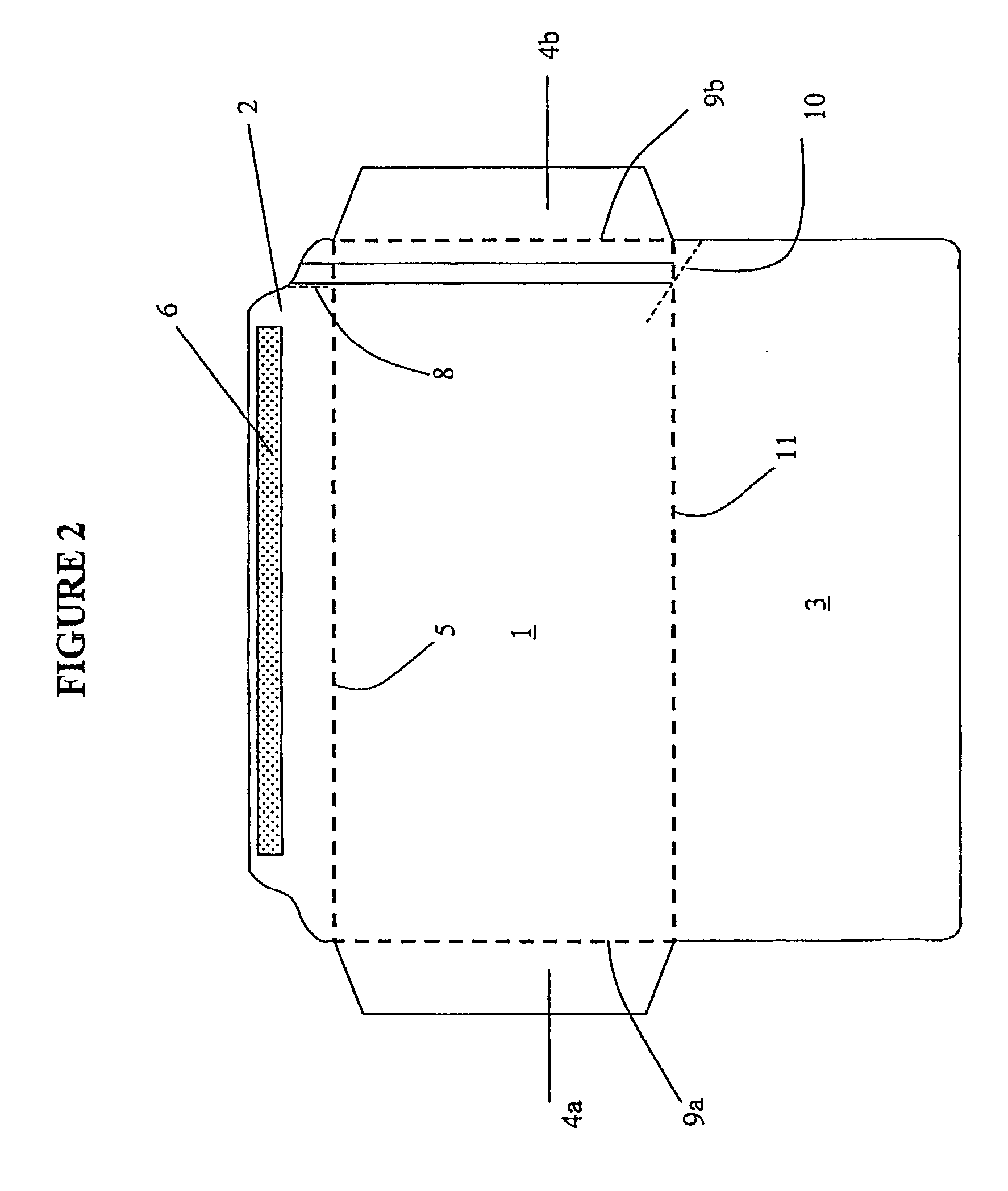
[0014] FIG. 1 represents one preferred embodiment of the present invention, in which the envelope 100 comprises a front panel 1, a seal flap 2 which is a vertical extension of the front panel 1, and which is separated from said front panel by a fold line 5; a rear panel 3 and side flaps 4a and 4b. Side flaps 4a and 4b are lateral extensions of the front panel 1, which are foldably connected to said front panel 1 via fold lines 9a and 9b. When the envelope is formed, side flaps 4a and 4b are folded under and attached to the interior of the rear panel 3. Seal flap 2, which is foldably connected via fold line 5 to the front panel 1, further includes an adhesive seal zone 6, which is coated with a gummy adhesive suitable for sealing the envelope 100. The gummy adhesive can be a self-sealing polymeric material, which may optionally be covered by a protective strip until it is desired that the envelope be sealed. Alternatively, the gummy adhesive may be of a type that requires moistening ...


PUM


Abstract

An envelope comprising a tear strip that functions as an efficient opening means for access to the envelope contents.

Description

TECHNICAL BACKGROUND AND FIELD OF APPLICABILITY OF THE INVENTION[0001] The invention is an easy to open envelope that provides the user easy access to its contents, by virtue of a tape strip located along one side edge of the envelope body.[0002] The stationery envelope has been an indispensable tool for communication throughout the last century, and, accordingly, much effort has been focused on making the design, manufacture and user-friendliness of this instrument more efficient and economical. In particular, several attempts have been made to improve the technical design of the envelope to allow the user easier access to the envelope contents, while at the same time reducing the risk of accidentally tearing the envelope body and damaging its contents or causing injury to the user.[0003] The use of tear guides has been one means of providing simple, controlled access to the envelope contents. For example, U.S. Pat. No. 2,161,958 (MacDonald) discloses an envelope in which a cutting...

Claims


Application Information

Patent Timeline
Patent Type & Authority Applications(United States)
IPC IPC(8): B65D27/38
CPCB65D27/38Y10S493/917Y10S493/931Y10S493/923
Inventor PURCELL, DOUGLAS K.
Owner ENVELOPE PROD GROUP
Why Eureka
Try Eureka