Remote patient monitoring system with garment and automated medication dispenser

a patient monitoring and remote patient technology, applied in the field of remote patient monitoring system with garment and automated medication dispenser, can solve the problems of inefficient and error-prone approach, inability of nursing personnel to monitor those remote patients in a cost-effective manner, and inability to keep accurate medication dose records

Inactive Publication Date: 2003-01-30
SHUSTERMAN LARRY
View PDF57 Cites 123 Cited by
  • Summary
  • Abstract
  • Description
  • Claims
  • Application Information

AI Technical Summary

Problems solved by technology

Where patients are recuperating at home or in far-flung branches of a large hospital, however, it is especially difficult for nursing personnel to monitor those remote patients in a cost-effective manner.
This approach is inefficient and error-prone, because the support personnel often split time between administering medication and performing other duties.
If the personnel are hurried, they may not keep accurate records of medication doses.
In addition, the medication doses may not be correct because a harried support person failed to fill the prescription properly.
Preferably, the patient monitoring system restricts access to the monitoring device to authorized personnel.

Method used


Image

  • Remote patient monitoring system with garment and automated medication dispenser
  • Remote patient monitoring system with garment and automated medication dispenser
  • Remote patient monitoring system with garment and automated medication dispenser

Examples


Embodiment Construction

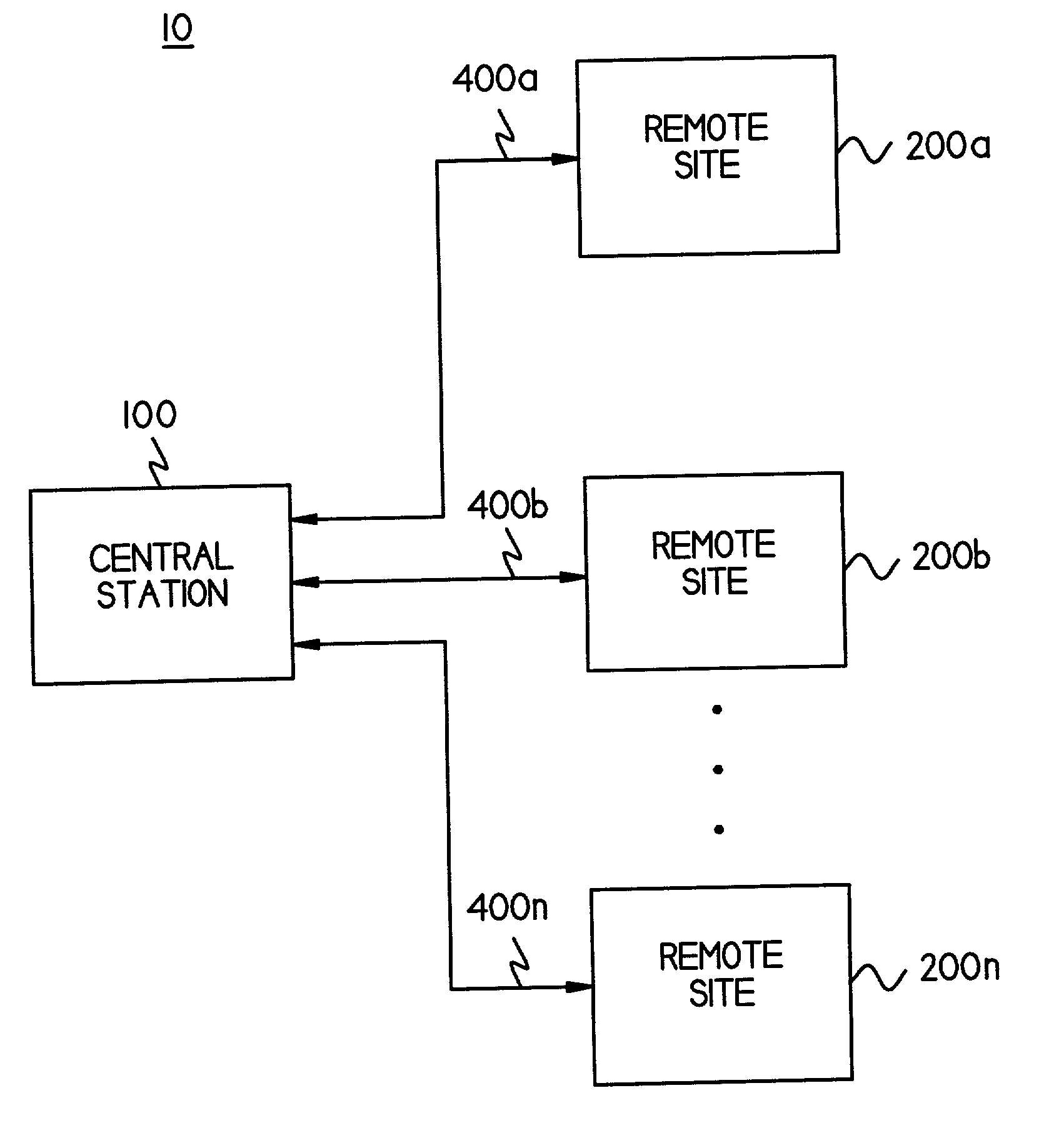
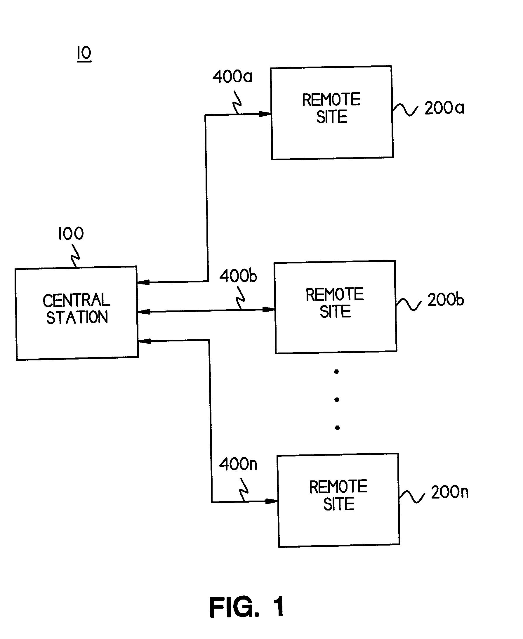
[0039] FIG. 1 is a block diagram of a remote patient monitoring system 10 constructed in accordance with the present invention. In a minimum configuration, system 10 includes central station 100 and one remote site 200. However, the system 10 can be extended to include any number of remote sites 200, limited only by the computational resources provided by central station 100. FIG. 1 illustrates an exemplary and not limiting embodiment including a plurality of remote sites 200a, 200b, . . . 200n.

[0040] Central station 100 exchanges commands and data with each remote site 200 over a communication link 400. As shown in FIG. 1, communication link 400a couples central station 100 with remote site 200a, communication link 400b couples central station 100 with remote site 200b, and communication link 400n couples central station 100 with remote site 200n. It will be understood that for each remote site 200 provided by system 10, a communication link 400 will couple that remote site 200 to ...


PUM


Abstract

The invention provides an integrated remote patient monitoring system that includes a garment, a monitoring device, and a medication dispensing unit. The garment is adapted for wearing by a patient, and is adapted to house at least one sensor that is in communication with the patient's body. The garment includes a connector communicating with the sensor. The monitoring device communicates with the sensor through the connector, and is configured to record signals from the sensor. The monitoring device is also configured to exchange signals representing patient status with a central station. The medication dispensing unit communicates with the monitoring device to receive commands from the monitoring device, and to transfer signals representing the status of medication doses to the monitoring device.

Description

[0001] This Application is a Continuation In Part of U.S. Non-Provisional patent application Ser. No. 09 / 126,662 Filed Jul. 30, 1998, which is U.S. Provisional Patent Application of U.S. Application No. 60 / 054,403 Filed Jul. 31, 1997.[0002] This invention pertains generally to patient monitoring, and more specifically to monitoring patient status and communicating with a patient from a point remote from the patient's location.BACKGROUND OF THE DISCLOSURE[0003] An ongoing concern in the medical profession is the containment of labor costs, especially the cost of nursing and other patient monitoring personnel. One way to minimize costs is to find ways to allow fewer nurses to monitor larger numbers of patients without jeopardizing patient safety. In addition, hospitals are discharging patients earlier, allowing them to recuperate at home rather than in the hospital. In a typical hospital setting, nurses must periodically check the patients' vital signs, to administer doses of medicine...

Claims


Application Information

Patent Timeline
Patent Type & Authority Applications(United States)
IPC IPC(8): A61B5/00A61B5/0205A61B5/021A61B5/024A61B5/08A61J7/00A61J7/04G06F19/00
CPCA61B5/02055A61B5/021A61B5/024A61B5/0816A61B5/1112A61B5/1117A61B5/411A61B5/4839A61B5/6805A61J7/0481A61J2007/0427A61J2007/049G06F19/322G06F19/3418G06F19/3462A61B5/0022A61B2505/07A61B2560/0242A61B2562/226A61J7/0084A61J2205/70A61J7/0427A61J7/049G16H10/60G16H20/13G16H40/67
Inventor SHUSTERMAN, D.O., LARRY
Owner SHUSTERMAN LARRY
Why Eureka
Try Eureka