Apparatus for measuring absorption dose distribution

a technology of absorption dose and measuring apparatus, which is applied in the direction of calibration apparatus, instruments, and can solve the problems of difficult to achieve accurate measurement of absorption dose patterns, difficult to secure measurement accuracy, and work on developing exposed x-ray films and measuring optical density requires a substantial amount of labor and tim

Inactive Publication Date: 2003-08-14
MITSUBISHI ELECTRIC CORP
View PDF12 Cites 15 Cited by
  • Summary
  • Abstract
  • Description
  • Claims
  • Application Information

AI Technical Summary

Problems solved by technology

However, the IMRT-dedicated absorption dosimeter utilizing the X-ray films as shown in FIG. 14 has a problem in that since the absorption characteristic of the X-ray films to absorb the radiation energies differs considerably from that of a human body, an accurate measurement of the absorption dose pattern is difficult to achieve.
Also, depending on the manufacturing lots and / or developing conditions of the X-ray films, output thereof tends to vary even though those X-ray films have absorbed an equal amount of radiation, resulting in difficulty to secure an measurement accuracy.
Also, the work of developing the exposed X-ray films and measuring the optical density requires a substantial amount of labor and a substantial amount of time.
However, scanning within the water phantom of the microchamber having a spatial resolving power of not greater than a few millimeter a substantial amount of labor and a substantial amount of time.
Yet, there is an additional problem in that since the sensitive region is so small, the output current is so low as to result in a low signal-to-noise (S / N) ratio.

Method used


Image

  • Apparatus for measuring absorption dose distribution
  • Apparatus for measuring absorption dose distribution
  • Apparatus for measuring absorption dose distribution

Examples


first embodiment

[0029] (First Embodiment)

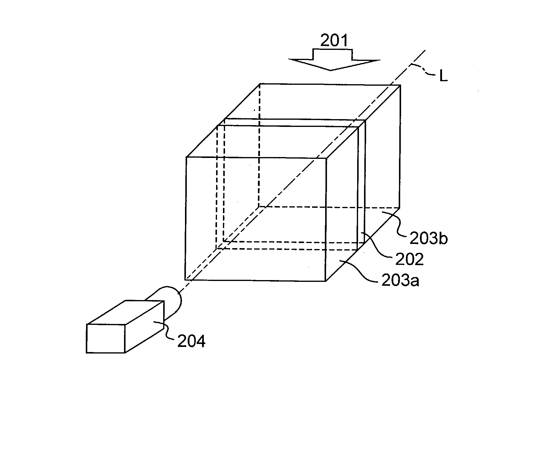
[0030] FIG. 1 illustrates the overall structure of a distribution-measuring apparatus (an apparatus for measuring absorption dose distribution) according to the first embodiment of the present invention. As shown therein, the distribution-measuring apparatus includes a phantom constructed of a plate-shaped plastic scintillator 202, a transparent plastic block 203a and a plastic block 203b and adapted to be irradiated with radiation 201 such as X-rays or particle beams such as electron beams. It is to be noted that the plastic blocks 203a and 203b are, when viewed in a direction shown by a straight line L, that is, in a direction of thickness of the plastic scintillator 202 (hereinafter referred to as "scintillator thickness direction"), arranged with opposite end faces (confronting in the scintillator thickness direction) of the plastic scintillator 202 sandwiched between the plastic blocks 203a and 203b.

[0031] When the phantom is irradiated with the radiati...

second embodiment

[0059] (Second Embodiment)

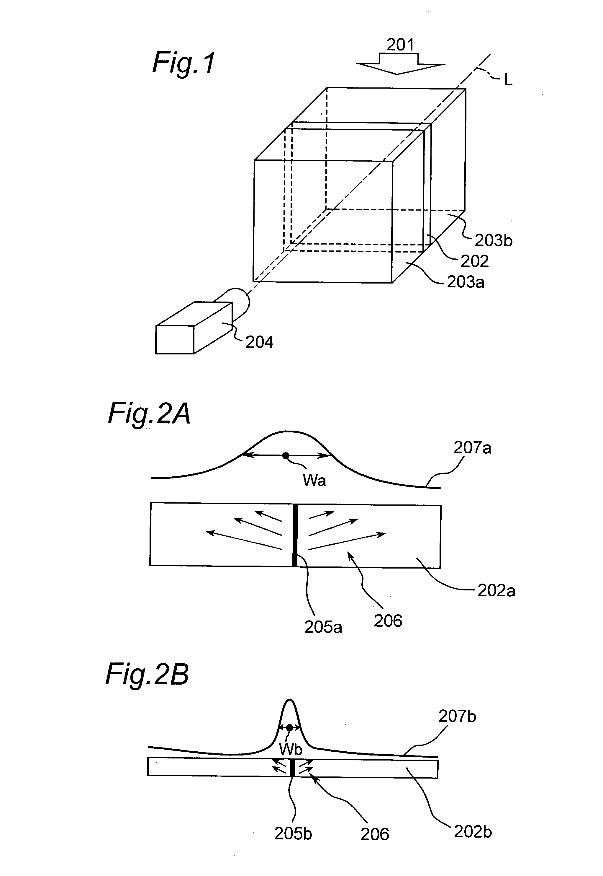
[0060] The second embodiment of the present invention will be described with reference to FIGS. 5A and 5B. The distribution-measuring apparatus according to this embodiment has numerous features common with the distribution-measuring apparatus according to the first embodiment of the present invention. Accordingly, in the following description, features and / or components similar to those of the distribution-measuring apparatus according to the first embodiment are not described to avoid repetition thereof and, instead, only differences from that according to the first embodiment will be described. Specifically, in the distribution-measuring apparatus according to the second embodiment, the surfaces of the plastic scintillator are polished to represent surfaces similar to an optical mirror surface, and other features and / or components thereof are substantially identical with those in the distribution-measuring apparatus according to the first embodiment.

[006...

third embodiment

[0065] (Third Embodiment)

[0066] The third embodiment of the present invention will be described with reference to FIG. 6. It is however to be noted that the distribution-measuring apparatus according to this embodiment has numerous features common with the distribution-measuring apparatus according to the first embodiment of the present invention and, accordingly, in the following description, features and / or components similar to those of the distribution-measuring apparatus according to the first embodiment are not described to avoid repetition thereof and, instead, only differences from that according to the first embodiment will be described. Specifically, in the distribution-measuring apparatus according to the third embodiment, the wavelength of light emitted from the plastic scintillator is set to a visible region ranging from a green region to a red region, while other features and / or components thereof are substantially identical with those in the distribution-measuring app...


PUM

PropertyMeasurementUnit
thicknessaaaaaaaaaa
thicknessaaaaaaaaaa
thicknessaaaaaaaaaa

Abstract

An apparatus for measuring absorption dose distribution may be used for radiotherapy such as IMRT and Radiosurgery. In the apparatus, measurement or evaluation of the distribution of the radiated dose within the phantom can be achieved accurately and in a relatively short length of time. The apparatus includes a phantom constructed of a plate-type plastic scintillator (202) having a thickness within the range of 0.15 to 1 mm and plastic blocks (203a) and (203b) positioned so as to sandwich the plastic scintillator (202) therebetween, and an image analyzer (204). At least one of the plastic blocks (203a) and (203b) is transparent and the image analyzer measures a pattern of intensity distribution of light emitted from the plastic scintillator (202) when the phantom is irradiated with radiation.

Description

[0001] 1. Field of the Invention[0002] The present invention relates to an apparatus for accurately and quickly measuring absorbed dose distribution in a phantom that is used in the course of a radiotherapeutic treatment of cancer using X-rays, particle beams such as electron beams or the like.[0003] 2. Description of the Prior Art[0004] In the intensity modulated radiotherapy (IMRT), one of the radiotherapeutic treatments, it has been a general practice to irradiate a patient by changing the field profile of radiation and, also, the direction of incidence of radiations so that the cumulative absorption dose of the radiations may be proportionated to an affected zone of the patient. Accordingly, the IMRT has been recognized having a merit in that the irradiations can be concentrated on the affected zone to enhance the radiotherapy.[0005] However, when it comes to performance of the IMT, a treatment plan has to be set up in which irradiating conditions required for the affected zone ...

Claims


Application Information

Patent Timeline
Patent Type & Authority Applications(United States)
IPC IPC(8): A61N5/10G01N23/06G01T1/02G01T1/203
CPCA61B6/583G01T1/203A61N5/1048A61N5/1042A61N2005/1076
Inventor NISHIZAWA, HIROSHISHIOMI, TOMOYUKISENOO, SATOSHI
Owner MITSUBISHI ELECTRIC CORP
Why Eureka
Try Eureka