
Multiple-use biopsy apparatus and corresponding single-use biopsy instrument

Inactive Publication Date: 2003-08-28
BIFOS
View PDF15 Cites 8 Cited by
  • Summary
  • Abstract
  • Description
  • Claims
  • Application Information

AI Technical Summary

Benefits of technology

[0010] It is an object of the invention to provide a biopsy apparatus comprising a loading assembly for multiple use in which a disposable biopsy instrument can be easily and safely mounted and dismounted.
[0016] According to a first preferred aspect of the invention, the cartridge lock extends outside the cartridge body opening and is displaceable in the lock plane in the direction of the cartridge body so as to cover the opening of the cartridge body opening more fully. It is advantageous for the cartridge lock to be securable in a displaced position at the cartridge body or at an element secured thereat.

Problems solved by technology

To this adds the sharp tip of the stylet and the front edge of the canula which may cause wounds if not properly handled in mounting or may be accidentally damaged, as may be the tiny tissue excision means, that is the finger of the finger tube.

Method used


Image

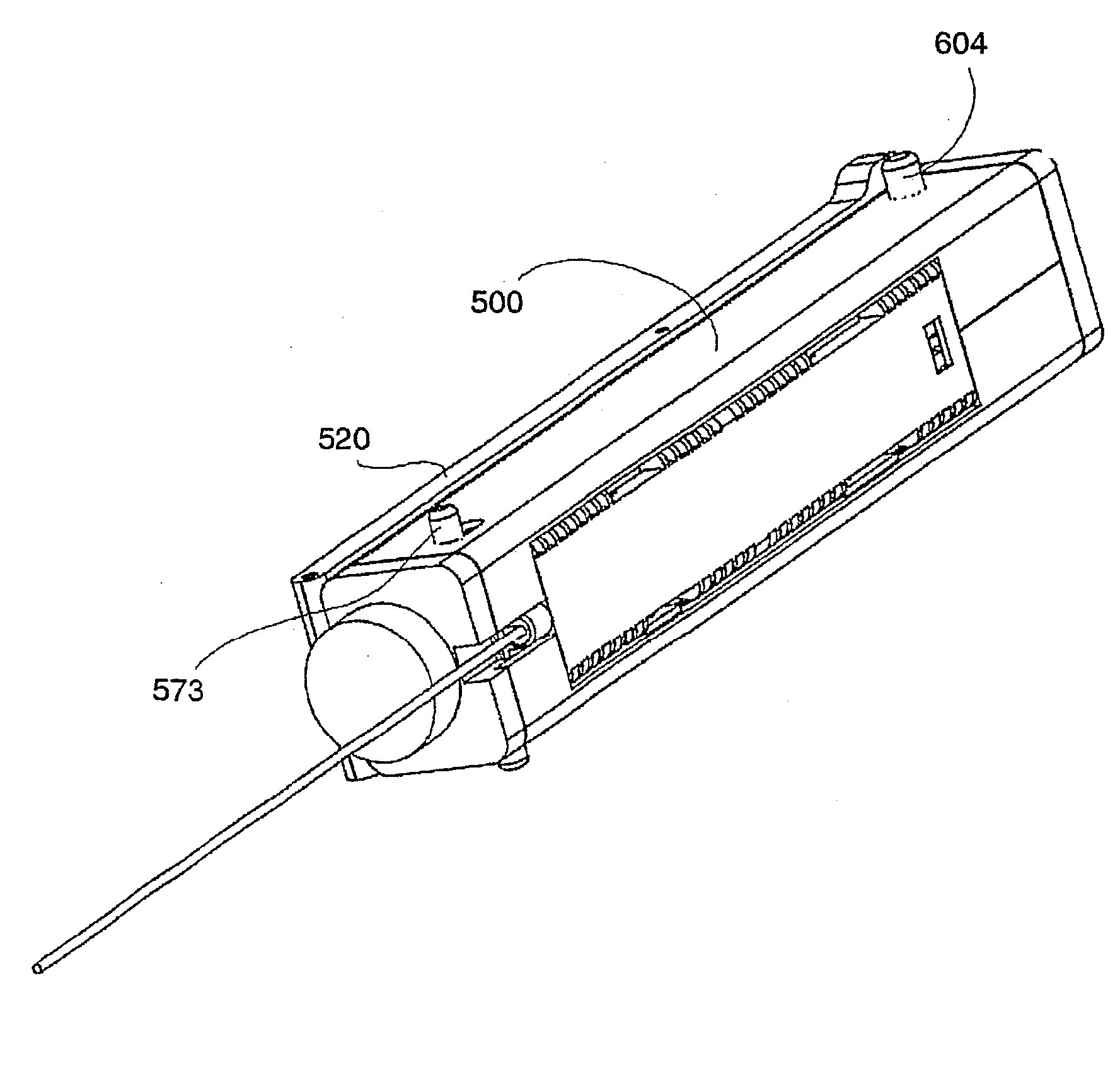
  • Multiple-use biopsy apparatus and corresponding single-use biopsy instrument
  • Multiple-use biopsy apparatus and corresponding single-use biopsy instrument
  • Multiple-use biopsy apparatus and corresponding single-use biopsy instrument

Examples


Embodiment Construction

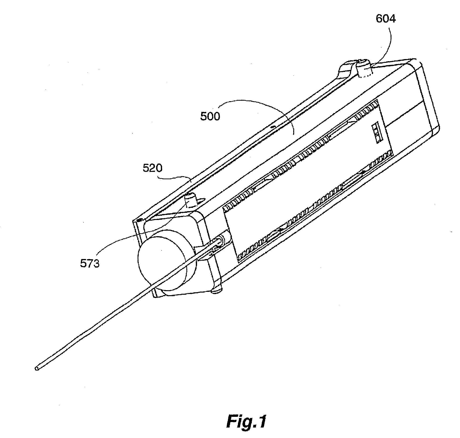
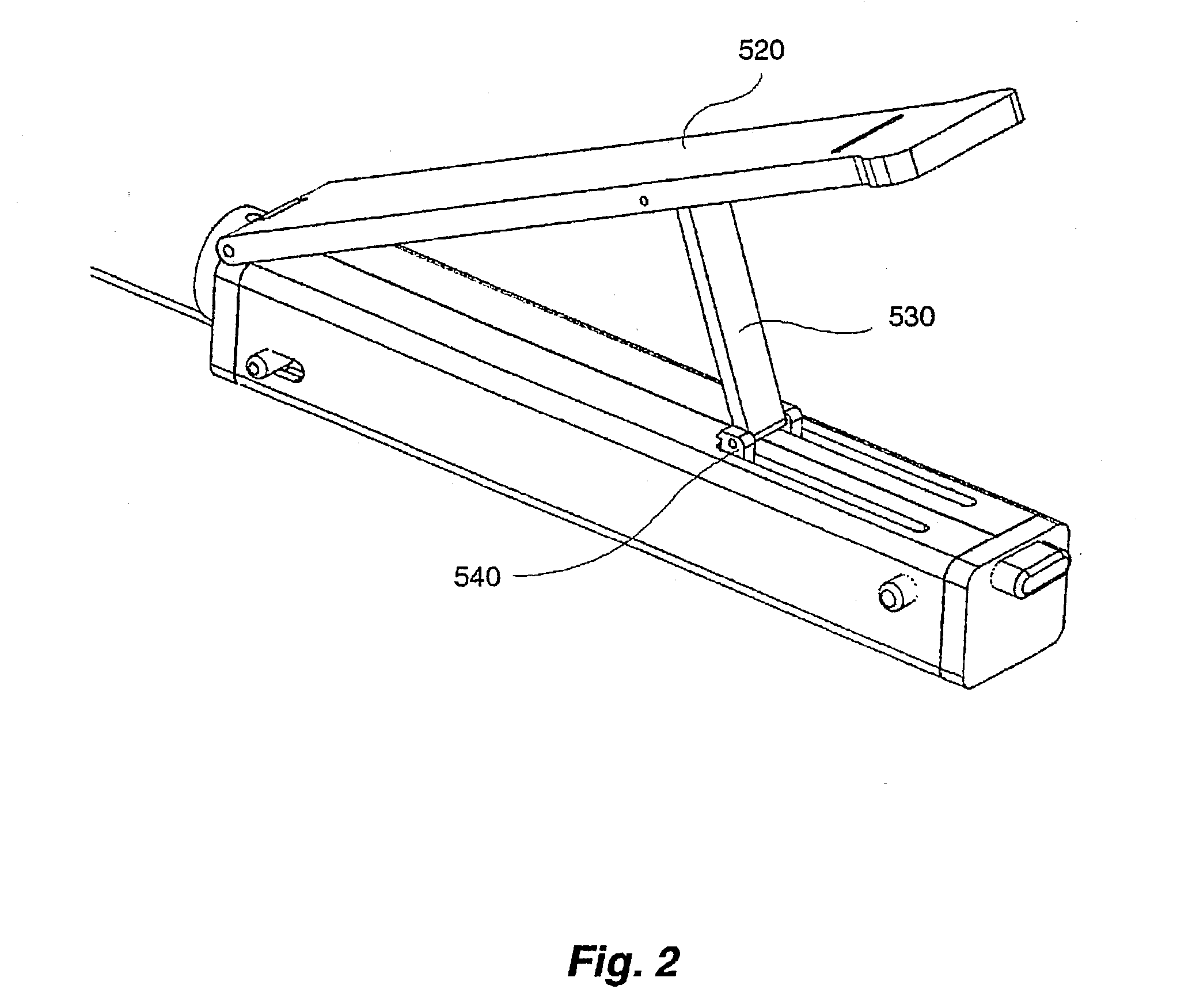
[0048] Indications of lateral direction such as `from above`, `underside`, `top side` are defined by the views of the Figures. The steel coil compression springs are only shown schematically as cylinders.

[0049] The biopsy instrument illustrated in FIGS. 1 and 13-19 comprises a canula, a finger tube 201 and a stylet 301 of the same kind as illustrated in FIG. 4 of WO 99 / 44505; see also U.S. Pat. No. 5,644,542, where the design and function of these elements is explained in detail and which is incorporated herein by reference. In FIG. 29 rear (proximal) end portions of the finger tube 201 enclosing the canula and the stylet 301 are shown to illustrate their relationship with their respective holders 200, 300, each made in one piece of a polymer material, preferably an ABS polymer (acrylonitrile-butadiene-styrene copolymer) or another polymer of high impact and tensile strength. Also shown in FIG. 29 is the canula holder 100.

[0050] The canula, the finger tube 201 and the stylet 301 are...


PUM


Abstract

A single-use biopsy instrument for mounting at a multiple-use biopsy apparatus, comprises a cartridge enclosing proximal end portions of a canula, a finger tube slidingly disposed on the canula, and a stylet slidingly disposed in the canula. The canula and the finger tube have proximal holding portions and are displaceable in regard of the cartridge by displacement means disposed in the biopsy apparatus engaging with the holding portions through one or several engagement openings in one wall of the cartridge. Also disclosed is a corresponding biopsy apparatus.

Description

[0001] The present invention relates to a multiple-use biopsy apparatus. The present invention also relates to a single-use biopsy instrument for use with the biopsy apparatus of the invention.[0002] The invention departs from an apparatus for collecting tissue samples by excising a segment from tissue, and a corresponding method for harvesting of tissue samples described in WO 99 / 44505 which is incorporated by reference into this specification. The biopsy apparatus of WO 99 / 44505 comprises a biopsy instrument and a holder.[0003] In this specification, the terms "proximal" and "distal" refer to the person extracting a biopsy sample; the terms "front" and "rear" have a corresponding meaning. Thus, the proximal end of a biopsy apparatus is its rear end, pointing away from the patient.[0004] The biopsy instrument of WO 99 / 44505 comprises a canula with a distal open cutting end and a through opening in its wall near the distal end, a finger tube slidingly disposed on the canula and prov...

Claims


Application Information

Patent Timeline
IPC IPC(8): A61B10/00A61B10/02
CPCA61B10/0233A61B2010/0208A61B10/0275A61B10/00
Inventor WEILANDT, ANDRESLINDGREN, MIKAELJEMSEBY, JOAKIM
Owner BIFOS
Learn More