Drawer stop device with dual-side mountable roller

a stop device and mountable roller technology, which is applied in the direction of drawers, furniture parts, domestic applications, etc., can solve the problems of the front edges of the doors bumping against scratching the inside surface of the doors, and especially bothersome, and the doors bumping against the protruding front edges of the drawers

Inactive Publication Date: 2003-09-18
MIZRAHI SHALOM
View PDF8 Cites 4 Cited by
  • Summary
  • Abstract
  • Description
  • Claims
  • Application Information

AI Technical Summary

Benefits of technology

0016] The improvement of the present invention thus allows a single drawer stop unit to be used for left and right-sided mounting at either the top or bottom sides of a cabinet drawer with an interchangeably mounted roller element. The drawer stop device can be packaged as a single set with a mountin

Problems solved by technology

However, if the doors are not fully opened, or if they swing back, it often happens that when the drawers are pulled out, their front edges bump against and scratch the inside surface of the doors.
This is especially bothersome if the cabinet doors are made of expensive wood or a custom finish.
Also, if a drawer is not returned to its fully retracted position, an attempt to close the cabinet doors can cause the doors to bump against the protruding front edges of the drawers.
After repeated use, scratch lines and other marks can become gouged into the doors and cr

Method used


Image

  • Drawer stop device with dual-side mountable roller
  • Drawer stop device with dual-side mountable roller
  • Drawer stop device with dual-side mountable roller

Examples


Embodiment Construction

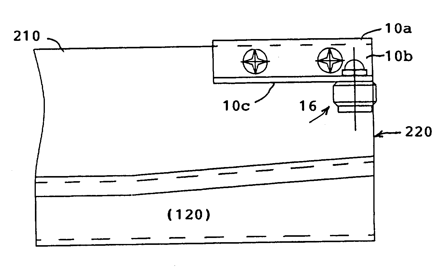
[0031] In accordance with the broad principles of the invention, the drawer stop device is formed as a single unit which can be mounted on both the left or right-handed sides of a drawer, and has dual-side mounting positions for the interchangeable roller element which is mounted with a spindle and cap nut assembly. In the following description, a specific embodiment is described to illustrate the principles of the invention. However, it is to be understood that other variations and modifications thereto may made.

[0032] As shown in FIG. 6A-6C, a preferred embodiment of the drawer stop device is formed as a single unit 10 having a Z-shape or 3-flange shape consisting of a first, horizontal flange 10a with a row of mounting holes 12 therein (aligned with a vertical hole axis A), a second, vertical flange 10b perpendicular to the first having another row of mounting holes 14 therein, and a third, horizontal flange perpendicular to the second and extending in an opposite horizontal dire...


PUM


Abstract

A drawer stop device having a dual-sided mounting portion and an interchangeably mountable roller element is used for both left and right-sided mounting for performing a bump-stop function on a sliding cabinet drawer. The mounting portion has a Z-shape or 3-flanged shape, including a first, horizontal flange provided with a row of mounting holes therein, a second, vertical flange perpendicular to the first and provided with another row of mounting holes therein, and a third, horizontal flange perpendicular to the second and extending in an opposite horizontal direction from the first and provided with a pair of roller mounting holes on opposite ends thereof. The interchangeable roller element is mounted by a spindle and cap nut assembly to one or the other mounting hole, depending on which handed side of the drawer the device is being mounted to. The device can be mounted using the mounting holes in the first, horizontal flange to the bottom portion of a standard sliding rail unit secured to the bottom edge of a sliding drawer, or using the mounting holes in the second, vertical flange to the side panel adjacent an front upper edge of the sliding drawer. The drawer stop device can be packaged as a single set with the mounting portion, the roller element, and the spindle and cap nut assembly for mounting in any desired position, thereby reducing the number of parts that need to be fabricated or stocked in inventory, as well as providing flexibility to mount the drawer stop device in any desired position.

Description

[0001] This U.S. patent application claims the priority benefit of U.S. Provisional Application No. 60 / 356,335, of the same inventor, filed on Feb. 13, 2002.[0002] This invention generally relates to an improvement in a drawer stop device, and more particularly, to a drawer stop device in which a single unit can be used for mounting on two opposite sides of a drawer.BACKGROUND OF INVENTION[0003] Sliding drawers are commonly built into kitchen cabinets, desks, dining room cabinetry, office furniture, and the like to provide more convenient access to storage space therein. Typically, the drawers are mounted behind cabinet doors which serve to close off and provide a clean, finished, external appearance when the cabinet is not in use. When access into the cabinet is desired, the doors are swung open to a position perpendicular or obtuse to the front plane of the cabinet, clearing the opening to allow a drawer to be slid out from the interior of the cabinet.[0004] However, if the doors ...

Claims


Application Information

Patent Timeline
IPC IPC(8): A47B88/00
CPCA47B88/00A47B95/043A47B88/50A47B88/919
Inventor MIZRAHI, SHALOM
Owner MIZRAHI SHALOM
Why Eureka
Try Eureka