Eureka AIR delivers breakthrough ideas for toughest innovation challenges, trusted by R&D personnel around the world.

Variable response bushing

a bushing and variable technology, applied in the direction of shock absorbers, mechanical equipment, transportation and packaging, etc., can solve the problems of passengers and drivers being significantly jarred by even the smallest bumps, and all bumps or deflections in the road should be absorbed

Inactive Publication Date: 2003-12-18
OMEGAD LLC
View PDF22 Cites 0 Cited by
  • Summary
  • Abstract
  • Description
  • Claims
  • Application Information

AI Technical Summary

Benefits of technology

[0010] The primary object of this invention is to provide a solution to the problems associated with the roll of the vehicle in a turn and, particularly, to absorb the effect of the small deflections.
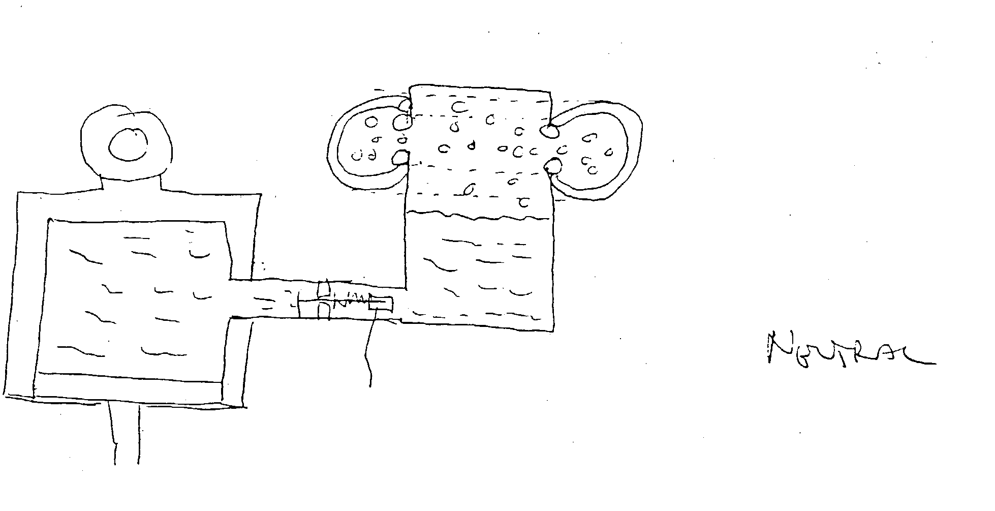
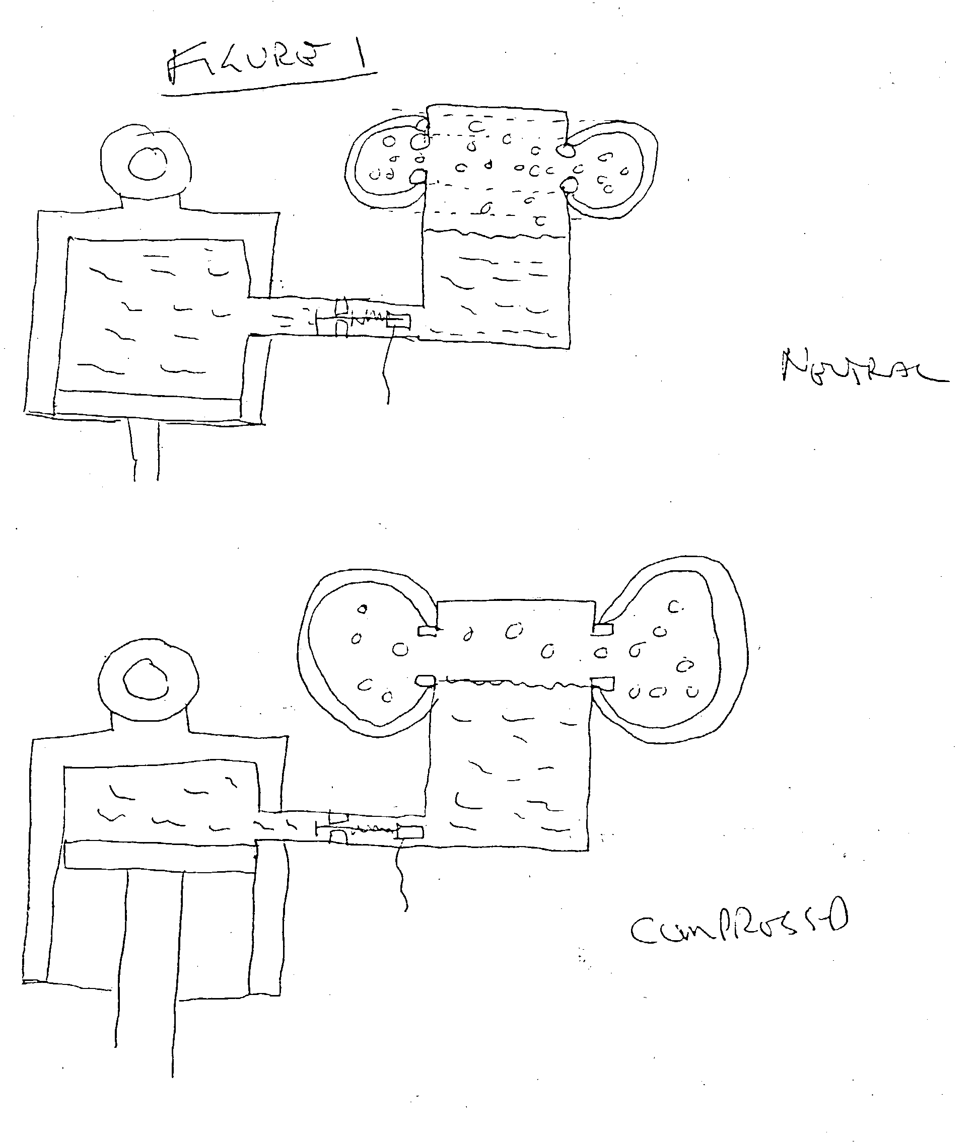
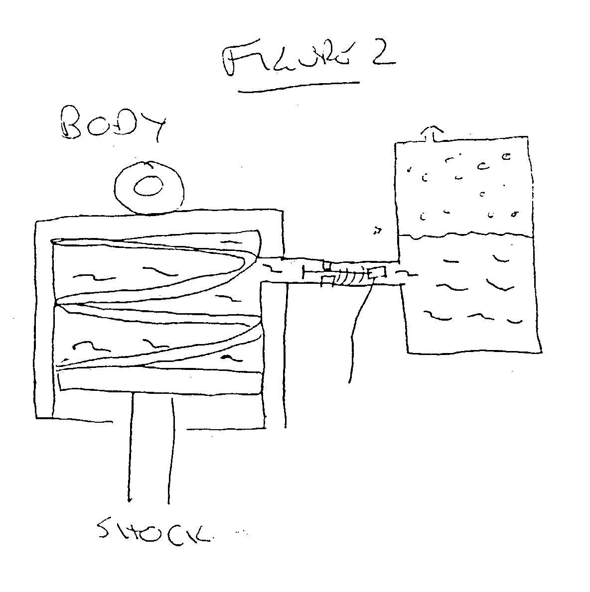
[0012] The objects of the invention are accomplished by a bushing of the present invention, which provides a variable and controllable means of cushioning. In straight line driving, the bushings can absorb a significant deflection, usually a two-inch deflection, but it may be much greater or smaller depending on the vehicle characteristics, thereby allowing the vehicle to absorb the bump. However, the bushings of the present invention also allow the vehicle to complete a turn with no roll from the bushings, as well as actively compensating for or preventing any roll from other suspension components. Depending upon the choice of the suspension system, the bushings of the present invention can be incorporated into a vehicle and can reduce or eliminate roll, allowing the ultimate control of the vehicle in a turn. A vehicle having the bushings of the present invention would have the ability to absorb small deflection bumps for passenger comfort, an important improvement over the prior art, while reducing or eliminating compression of the bushing in a turn to significantly reduce roll.

Problems solved by technology

A problem that can face vehicles is that all bumps or deflections in the road should be absorbed to avoid affecting the driver and passengers.
However, when the same vehicle enters a turn, the tire gives or deforms as pressure is applied to it from the body of the vehicle above.
However, when the vehicle encounters a small deflection the tire does not deform as much as regular tires and the passengers and driver can be significantly jarred by even the smallest bumps.
However, with any of the systems, even if the shock absorber is very firm, the vehicle can still roll in a turn due to the deformation of the tire and the compression of the bushing.
However, when the vehicle enters a turn there still will be roll from the bushings very quickly from compression of the air and then further from compression of the rubber.

Method used


Image

  • Variable response bushing
  • Variable response bushing
  • Variable response bushing

Examples


second embodiment

[0023] A second embodiment includes a coiled spring resting on top of the piston within the housing. Its function is to help return the bushing to the starting or neutral position. The second chamber would then be a reservoir for the fluid movement.

third embodiment

[0024] In a third embodiment, the second chamber contains a pressurized gas, such as nitrogen, on top of a float separating the fluid from the gas. The pressure of the nitrogen could be variably adjusted to allow compression to absorb the deflection and then the expansion of the nitrogen would return the busing to the neutral position. The pressure of the nitrogen or other gas could be actively varied to compensate for different driving conditions.

[0025] A variety of further embodiments can be used for the sealing means. These can include pressurized fluid, regulated from a pump, such as that found in the power steering mechanism of a vehicle. The pressurized power steering fluid can be attached to the second chamber. In this complicated embodiment, one would probably still require a sealing means to prevent back flow into the power steering reservoir and beyond, depending upon the pressures achieved by the bushing and power steering pump. Pressure sensors in the first and second ch...


PUM


Abstract

A bushing having a variable and controllable hardness, and a method of restricting movement comprising using such bushing.

Description

[0001] This application claims the benefit of U.S. Provisional Application No. 60 / 365,388, filed Mar. 18, 2002.[0002] This invention relates to a method and apparatus for controlling tilt or roll of a moving vehicle, particularly during a turn of the moving vehicle. The method and apparatus can also be used in a wide variety of other applications.[0003] Typically, a vehicle has a suspension system to help cushion the ride to the driver and passengers and to help the vehicle safely negotiate corners. The components of this suspension system can include the following: Tires, which deform to absorb bumps and return to previous size; Springs, which cushion impact; Shock absorbers located between the axle or frame or struts as part of the axle assembly to dampen the effect of impact, and; Bushings which are placed between the junctions of the above components usually made of rubber.[0004] A problem that can face vehicles is that all bumps or deflections in the road should be absorbed to ...

Claims


Application Information

Patent Timeline
IPC IPC(8): B60G17/015B60G7/00B62D5/07F16F9/08F16F9/096F16F9/50F16F9/58F16F13/28
CPCB60G7/006B60G2400/05F16F13/28F16F9/096F16F9/081
Inventor SMITH, S. GREGORYBEITZEL, JEFFREY
Owner OMEGAD LLC
Why Eureka
Eureka Blog
Learn More