Endoscope with sideview optics

a technology of optics and endoscopes, applied in optics, telescopes, medical science, etc., can solve the problems of affecting the reflected image of the object to be examined, reducing the illumination of the wall areas to be examined, and enlarge the field of view

Inactive Publication Date: 2004-01-22
ZAAR KERSTEN
View PDF12 Cites 184 Cited by
  • Summary
  • Abstract
  • Description
  • Claims
  • Application Information

AI Technical Summary

Problems solved by technology

Such an enlargement of the field of view is however, accompanied by a very burdensome reduction of the illumination of the wall areas to be examined.
In particular with smaller endoscopes these crosspieces may not exceed a certain strength, so that as a result the reflected image of the object to be examined can be disturbed, by for example having deciding damaged areas of the tube inside wall covered by a crosspiece.
Moreover, these crosspieces can get into the cone of the light illuminating the inside wall, so that shadows are formed, which can also result in the damaged areas of the object to be examined remaining undetected.
Further, there is the danger that crosspieces will reflect the light serving for illumination, so that a video camera with automatic exposure setting picks up the strongly illuminated crosspiece, but not the darker background, i.e. the object to be examined.

Method used


Image

  • Endoscope with sideview optics
  • Endoscope with sideview optics
  • Endoscope with sideview optics

Examples


Embodiment Construction

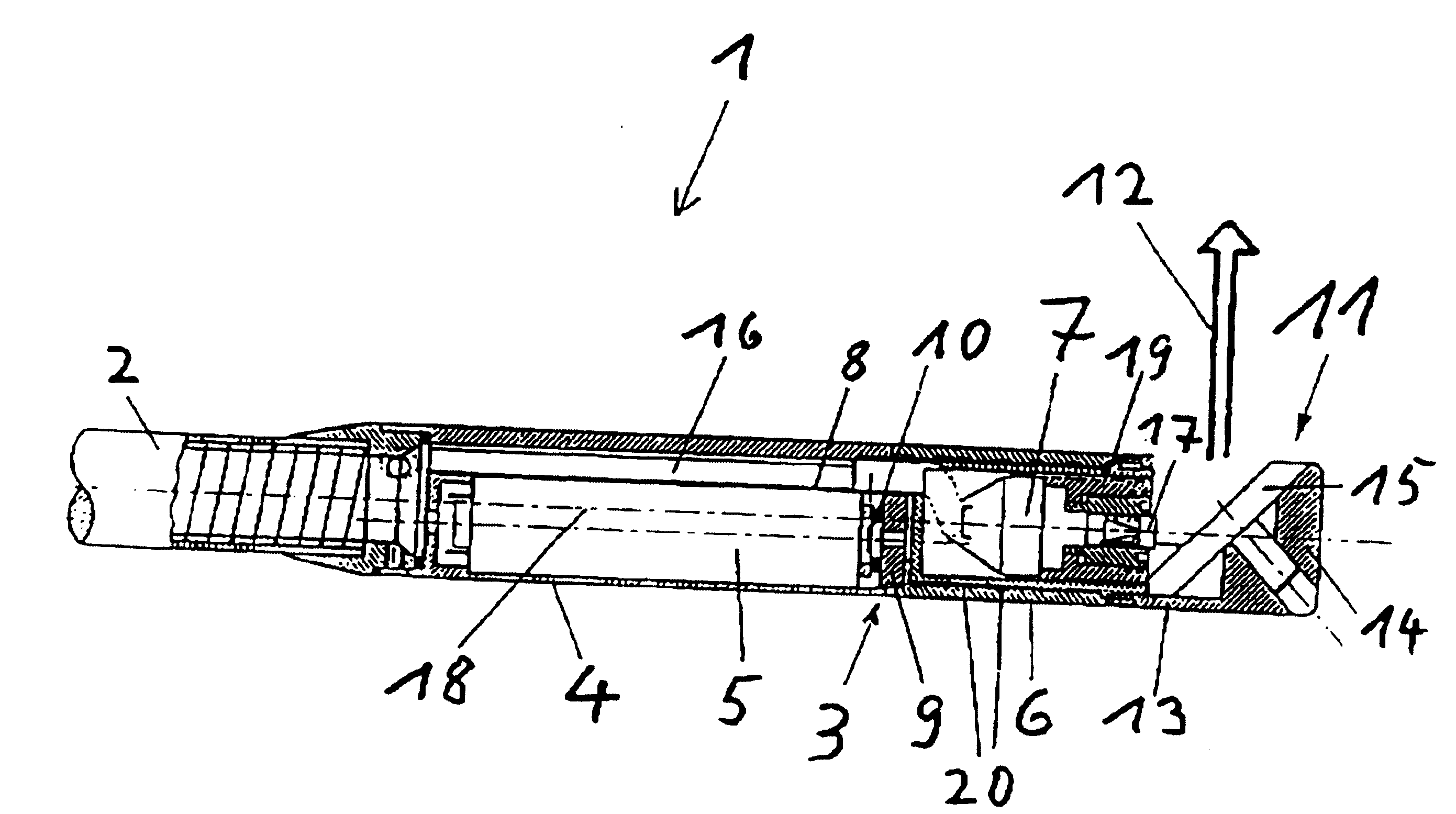
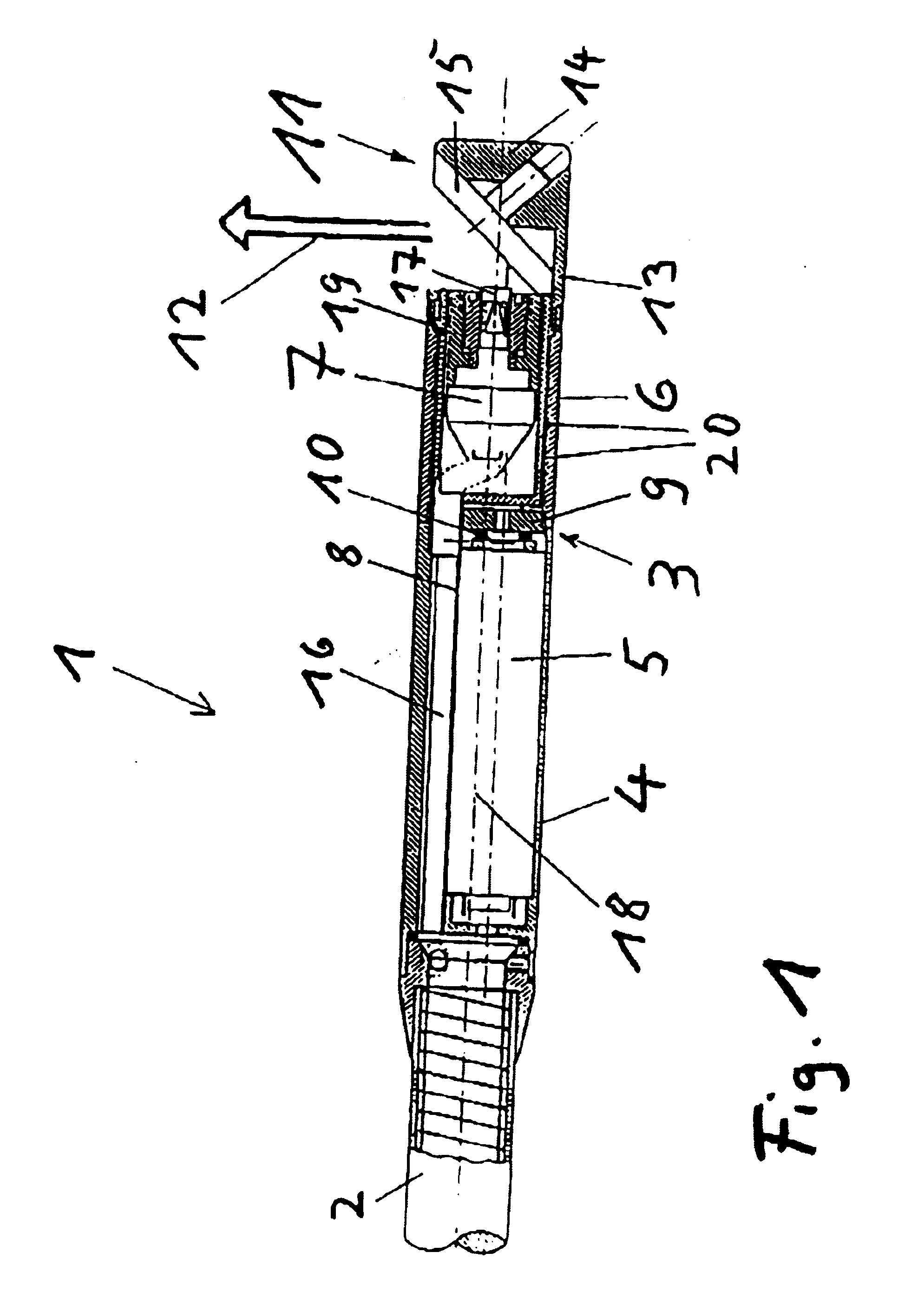
[0025] In FIG. 1 an endoscope 1 is shown with a probe 2 and a photo camera 3 attached to it. The photo camera 3 has a casing 4 connected with the probe 2 for an electric motor 5 and a rotating hollow cylinder 6 connected to it, in whose interior a video camera 7 in miniature format is arranged, as normally used for endoscopes and which is not explained in detail here. The video camera 7 is connected to a device for evaluating the supplied video signals by means of an electrical line conducted in the probe 2 and not shown in the figure and is connected with the casing 8 of the electric motor 5, which by means of a gear 9 thus can only rotate the hollow cylinder 6, which for this purpose in the area of the gear 9 has a hollow gear not shown in detail. Further, for this purpose there is a transmission 10 between the electric motor 5 and the gear 9 which reduces the speed of the electric motor 5 in suitable fashion. During one rotation of the hollow cylinder 6 the video camera 7 remains...


PUM


Abstract

An endoscope (1) is proposed with a rotatable side-viewing optics system (11), which has a mirror (15) for deflecting light onto an object to be examined and for reflecting the image of the object. A video camera (7) is located inside a hollow cylinder (6) that can be moved in rotation and the side-viewing optics system (11) is mechanically connected to the hollow cylinder (6) on the side that faces away from the viewing direction (12) of the video camera (7).

Description

STATE OF THE ART[0001] The invention starts from an endoscope with sideview optics according to the category of the main claim.[0002] Endoscopes with sideview systems for viewing and critically examining tubular inside walls and joints are known from the state of the art, with which a desired deviation of the field of view can be achieved. For this purpose optical systems can be used which consist of a deviation optics that can be rigidly mounted to an endoscope or a tubular camera, but which do not have a motor driven swivel head, so that only a small area of the tube inside wall can be examined. To enlarge the field of view of the tubular camera, an optics was created with a continuous 360.degree. panoramic view, which allows a view of the tube inside wall along with the view of the front. Such an enlargement of the field of view is however, accompanied by a very burdensome reduction of the illumination of the wall areas to be examined.[0003] To focus the existing light quantity o...

Claims


Application Information

Patent Timeline
Patent Type & Authority Applications(United States)
IPC IPC(8): G02B23/24
CPCA61B1/00177G02B23/2423A61B1/0669A61B1/0615G02B23/2484
Inventor ZAAR, KERSTEN
Owner ZAAR KERSTEN
Why Eureka
Try Eureka