Method and device for automatic control of an aircraft deceleration in running phase

a technology of automatic control and aircraft deceleration, which is applied in the direction of automatic braking sequence, aircraft braking arrangements, braking systems, etc., can solve the problem that predetermined braking set-points do not make it possible to optimise the strip occupation tim

Inactive Publication Date: 2004-02-12
AIRBUS OPERATIONS (SAS)
View PDF9 Cites 21 Cited by
  • Summary
  • Abstract
  • Description
  • Claims
  • Application Information

AI Technical Summary

Problems solved by technology

The use of predetermined braking set-points does not make it possible to optimise the strip occupation time on landing.

Method used


Image

  • Method and device for automatic control of an aircraft deceleration in running phase
  • Method and device for automatic control of an aircraft deceleration in running phase
  • Method and device for automatic control of an aircraft deceleration in running phase

Examples


Embodiment Construction

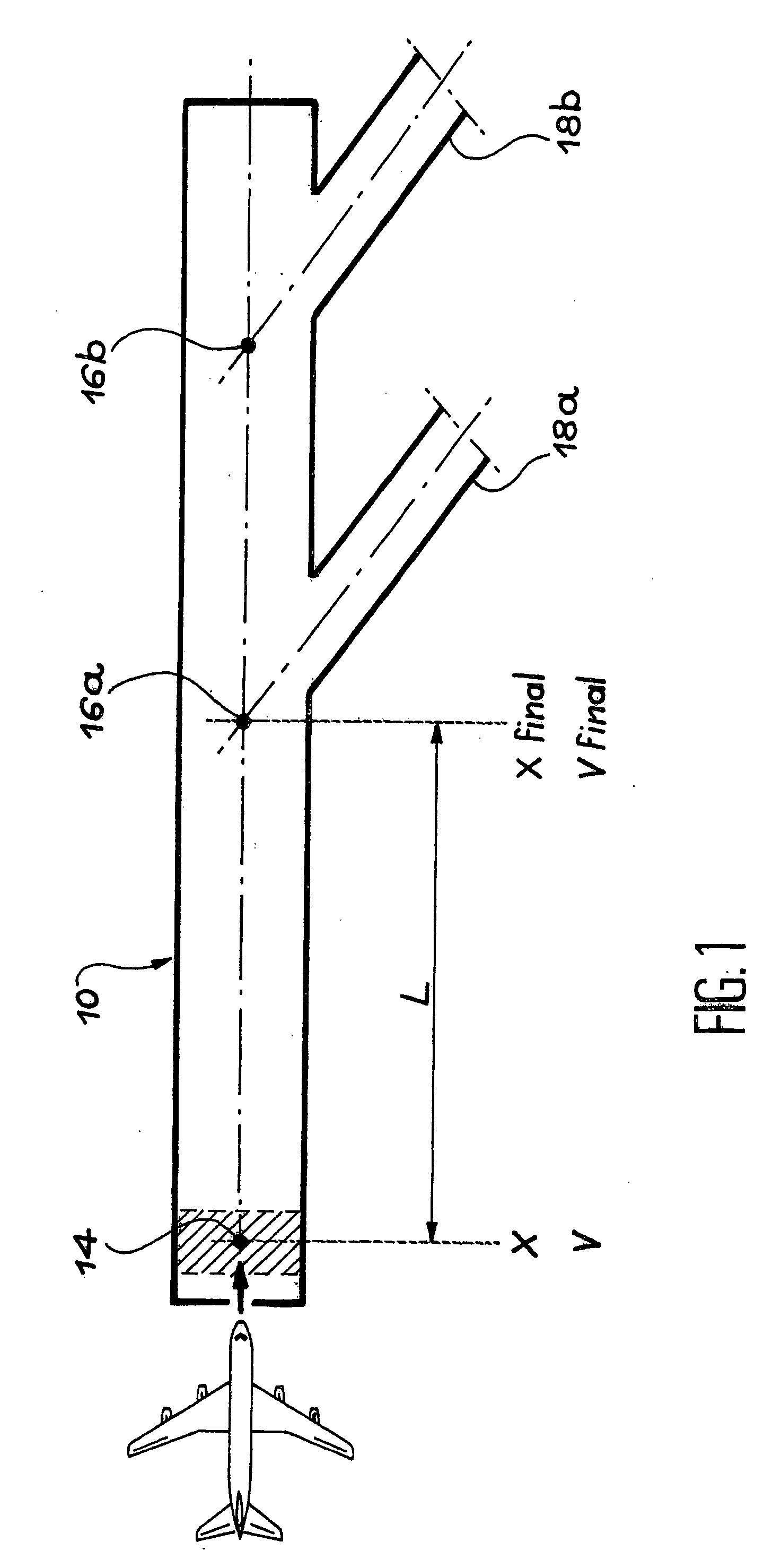
[0013] To achieve these aims, the invention more specifically relates to a system to control the deceleration of an aircraft during the taxiing phase on a landing strip, the system comprising:

[0014] acquisition means of the current (instantaneous) position of the aircraft on the strip,

[0015] acquisition means of the current (instantaneous) speed of the aircraft on the strip,

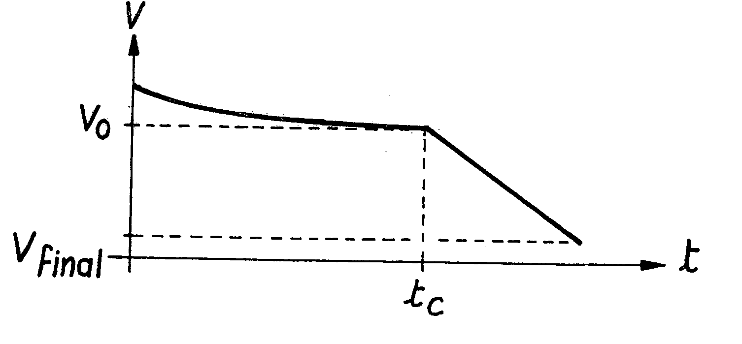
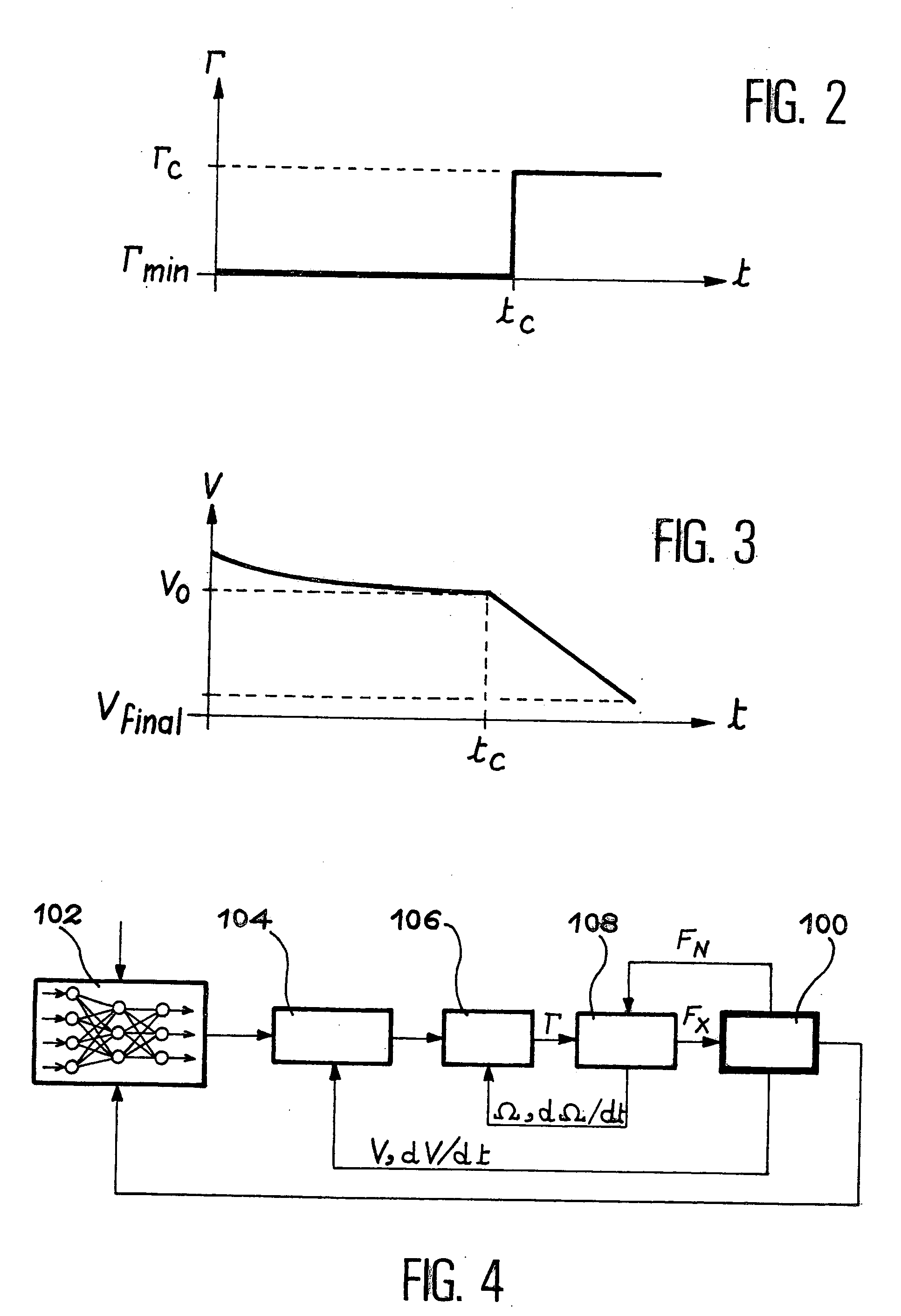
[0016] calculation means (102), receiving position and speed values from the acquisition means, to define, as a function of the desired final speed of the aircraft at the so-called final position on the strip, a deceleration set-point modification time, after the current time, and a new deceleration set-point to apply from the modification time, to reach the final position at the desired speed.

[0017] The above-mentioned final position is, for example, the position of an exit junction of the landing strip. The aircraft must reach this position at a sufficiently low final speed to leave the strip in complete safety...


PUM


Abstract

The invention relates to a system to control the deceleration of an aircraft during the taxiing phase on a landing strip, the system comprising: acquisition means (100) of the current position of the aircraft on the strip, acquisition means (100) of the current speed of the aircraft on the strip, calculation means (102), receiving position and speed values from the acquisition means, to define, as a function of the desired final speed of the aircraft at the so-called final position on the strip, a deceleration set-point modification time, after the current time, and a new deceleration set-point to apply from the modification time, to reach the final position at the desired speed.

Description

[0001] This application claims priority based on International Patent Application No. PCT / FR01 / 03923, entitled "Method And system For The Automatic Control Of Aircraft Deceleration During The Taxiing Phase" by Fabrice Villaume, which claims priority of French application no. 00 / 16147, filed on Dec. 12, 2000, and which was not published in English."[0002] The present invention relates to a method and system for the automatic control of the deceleration of an aircraft during the taxiing phase.[0003] A distinction is generally made, when an aircraft is being landed, between three steps which are: the approach phase, impact and the taxiing phase of the aircraft on a landing strip. The taxiing phase is used to decelerate the aircraft, so as to enable it to turn into an exit junction of the landing strip, thus freeing said strip.[0004] Due to chronic congestion in airports, and the costs associated with the use of landing strips, efforts have been concentrated on reducing the time during ...

Claims


Application Information

Patent Timeline
Patent Type & Authority Applications(United States)
IPC IPC(8): B64C25/42
CPCB64C25/426
Inventor VILLAUME, FABRICE
Owner AIRBUS OPERATIONS (SAS)
Why Eureka
Try Eureka