Strobe light emitting apparatus and camera

Inactive Publication Date: 2004-03-25
OLYMPUS CORP
View PDF1 Cites 84 Cited by
  • Summary
  • Abstract
  • Description
  • Claims
  • Application Information

AI Technical Summary

Problems solved by technology

When a shooting person generally shoots by holding a camera, a camera blur may occur during the exposure, which results in a mistake photograph.

Method used


Image

  • Strobe light emitting apparatus and camera
  • Strobe light emitting apparatus and camera
  • Strobe light emitting apparatus and camera

Examples


first embodiment

[0163] First of all, a strobe apparatus will be described as the invention.

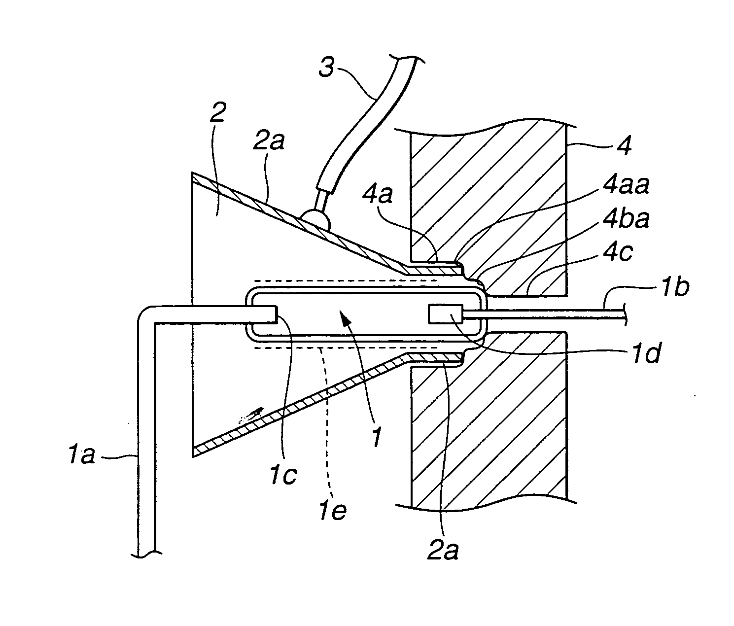
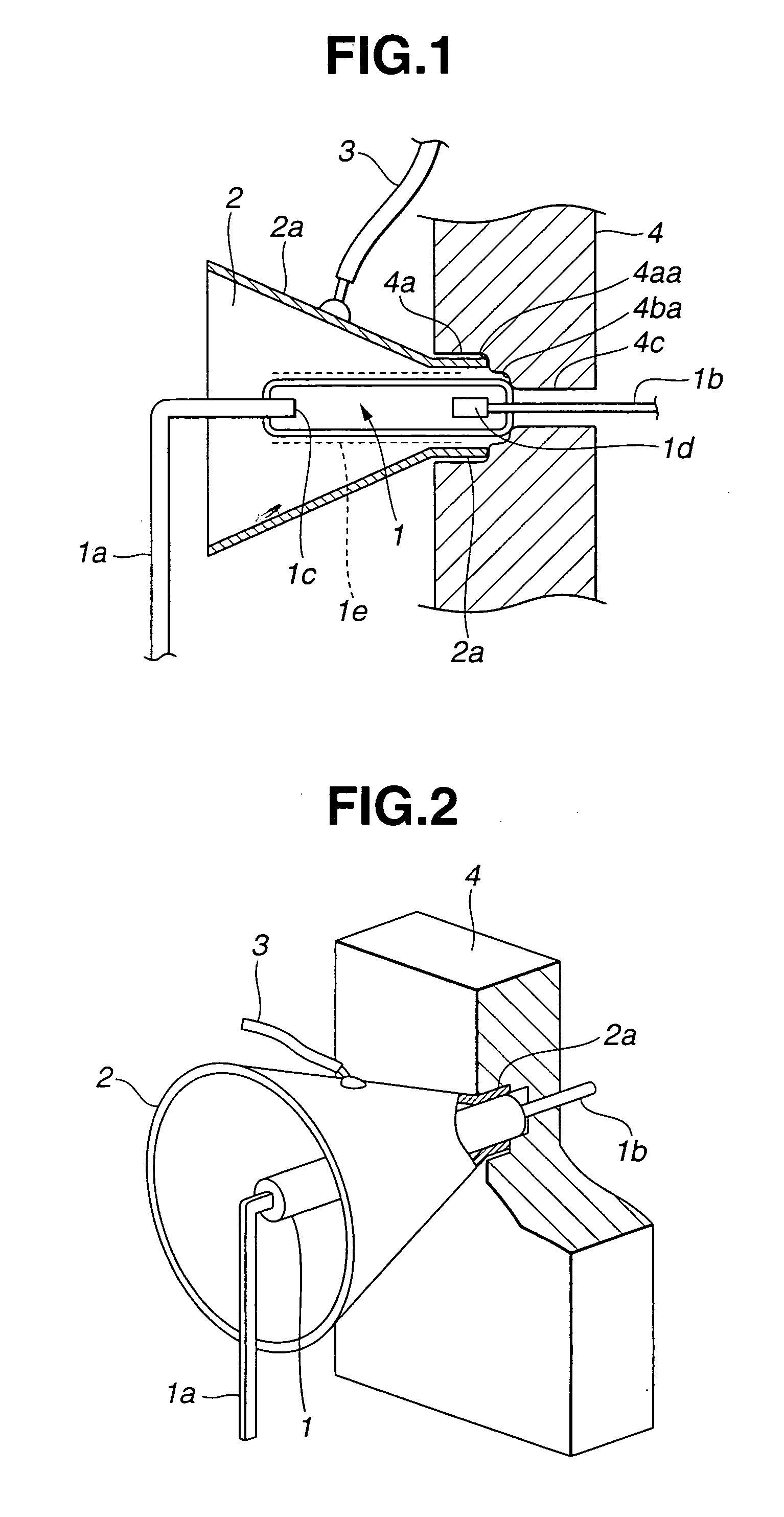
[0164] FIG. 1 is a section diagram showing a construction of the strobe apparatus according to the first embodiment. FIG. 2 is a perspective diagram showing a light emitting part of the strobe apparatus having a partial section.

[0165] Xenon gas is filled within a xenon tube 1, which is strobe light emitting discharge tube. The xenon tube 1 has terminals 1a and 1b extending outward from the both sides. The terminal 1a extends in a light irradiating direction. The terminal 1b extends in the direction of a fixed member 4 of the body. The terminal 1a bends in a direction at right angles to the xenon tube 1 and is electrically connected to a lead line or substrate, not shown. On the other hand, the terminal 1b extends linearly to the xenon tube 1 and is electrically connected to a lead line or a substrate, not shown.

[0166] The terminals 1a and 1b extend from the end within the xenon tube 1. An anode 1c is provided...


PUM


Abstract

A strobe apparatus of the present invention has a xenon tube, which is a discharge tube, having a discharge light emitting portion and a light emitting portion terminal. Light is emitting from the xenon tube and is reflected in a predetermined direction by a reflection umbrella. A transparent electrode is coated on the external surface of the xenon tube from the discharge light emitting portion to the terminal. When trigger voltage is applied to the xenon tube through the transparent electrode, strobe light is emitted by the discharge light emitting portion. By using the strode apparatus, the orientation characteristic of the discharge tube can be improved without uneven light distribution and a shortage of a light amount.

Description

[0001] This application claims benefit of Japanese Applications No. 2002-165724 filed in Japan on Jun. 6, 2002-180136 filed in Japan on Jun. 20, 2002, No. 2002-188366 filed in Japan on Jun. 27, 2002, No. 2002-192449 filed in Japan on Jul. 1, 2002, No. 2002-204365 filed in Japan on Jul. 12, 2002 and No. 2002-204367 filed in Japan on Jul. 12, 2002, the contents of which are incorporated by this reference.[0002] 1. Field of the Invention[0003] The present invention relates to a strobe light emitting apparatus (strobe apparatus) for emitting light by using a strobe light emitting discharge tube, a light system construction of a strobe light emitting apparatus, a light emitting circuit for a strobe light emitting apparatus and a camera having a camera blur preventing function.[0004] 2. Related Art Statement[0005] Conventionally, in a strobe apparatus (strobe light emitting apparatus) using a parabolic reflection umbrella of a camera including a digital camera, trigger voltage may be appl...

Claims


Application Information

Patent Timeline
Patent Type & Authority Applications(United States)
IPC IPC(8): G03B15/03G03B15/05G03B17/02H04N5/225H04N5/232H05B41/32
CPCG03B15/03G03B15/05G03B17/02G03B2215/0521H05B41/32H04N5/23212H04N5/23248H04N5/23264H04N5/2256H04N23/56H04N23/671H04N23/65H04N23/68H04N23/682
Inventor TSUCHIDA, KEIICHIMIKAMI, KAZUOSUZUKITERADA, HIROSHI
Owner OLYMPUS CORP
Why Eureka
Try Eureka