Sawdust collection assembly for a compound miter saw

Inactive Publication Date: 2004-04-01
P & F BROTHER INDAL
View PDF6 Cites 37 Cited by
  • Summary
  • Abstract
  • Description
  • Claims
  • Application Information

AI Technical Summary

Problems solved by technology

However, a lot of sawdust is generated when the circular saw cuts a workpiece, and the sawdust can and does interfere with subsequent cutting operations.
The conventional sawdust collection system cannot keep the cutting groove (35) completely clear of debris and sawdust.
Otherwise, the sawdust and debris will adve

Method used


Image

  • Sawdust collection assembly for a compound miter saw
  • Sawdust collection assembly for a compound miter saw
  • Sawdust collection assembly for a compound miter saw

Examples


Embodiment Construction

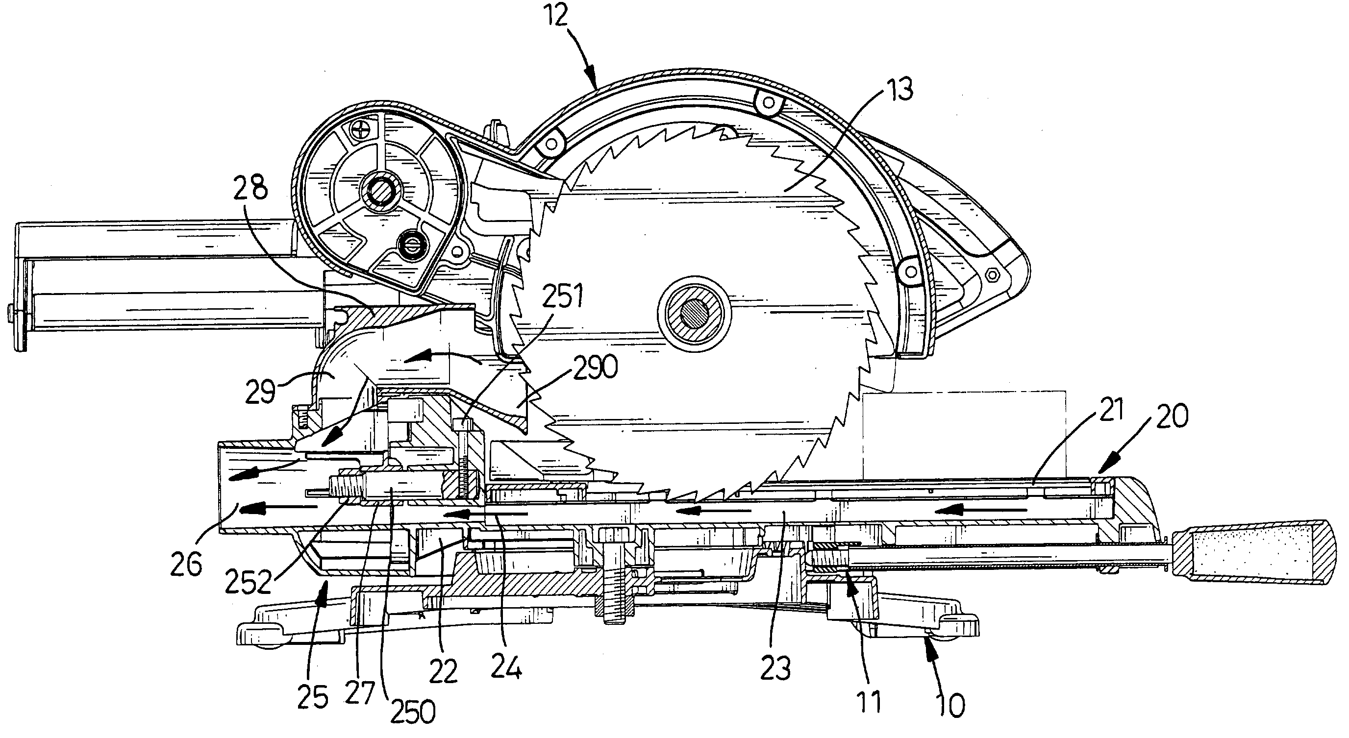
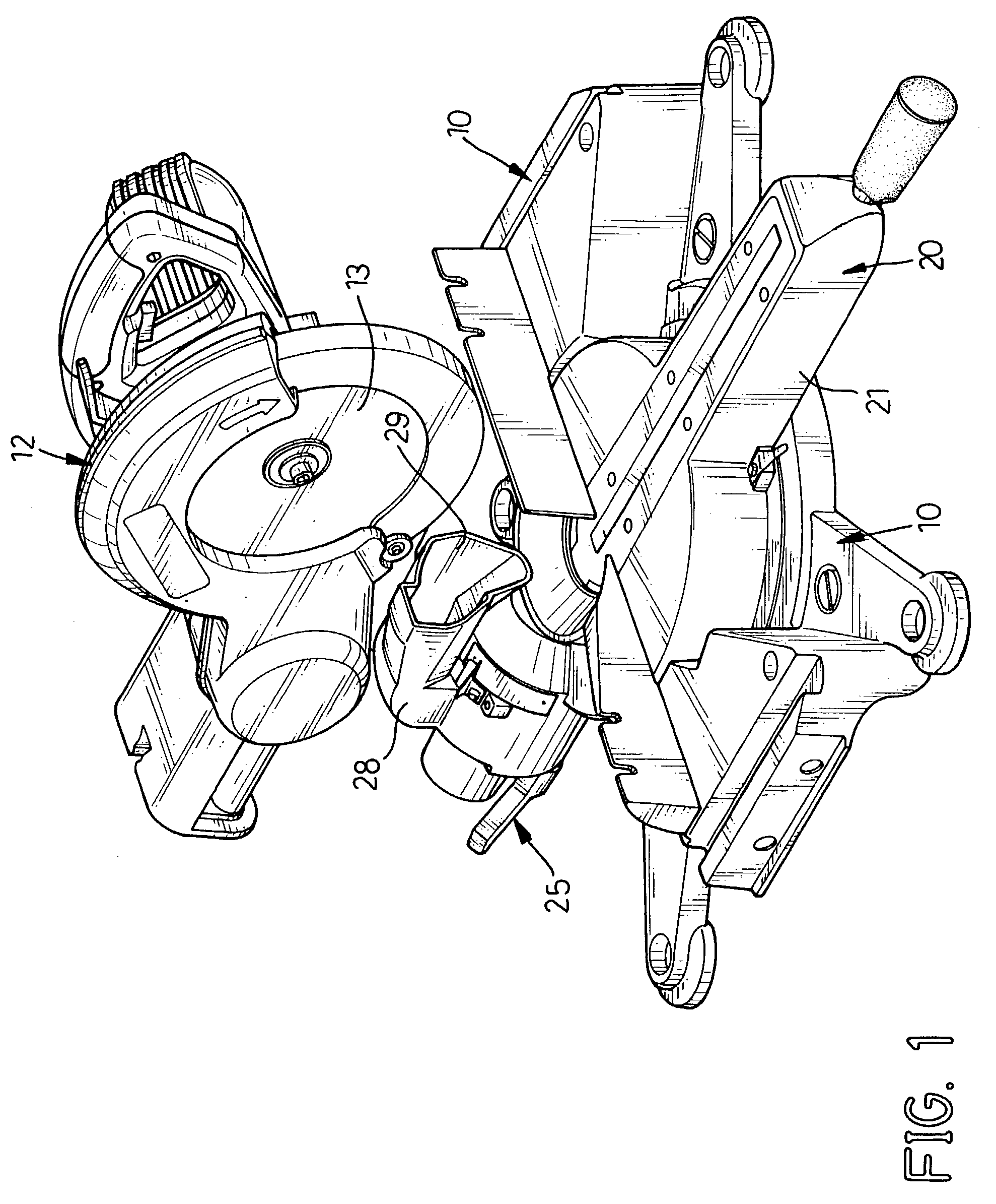
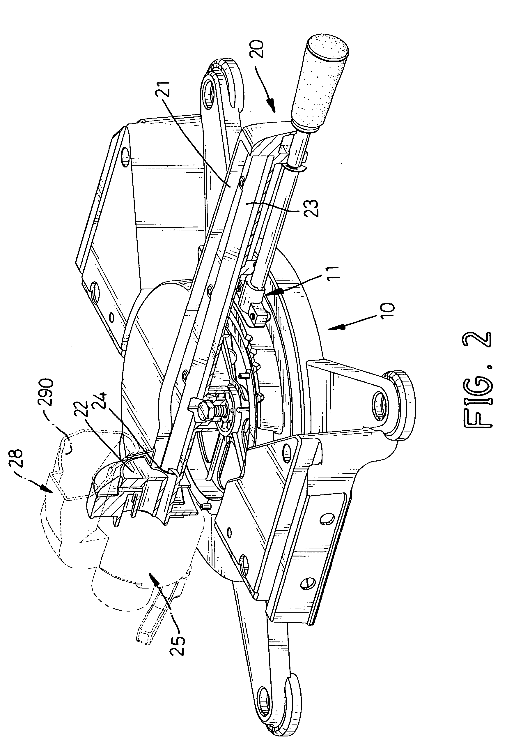
[0017] With reference to FIGS. 1 through 3, a compound miter saw typically comprises a base assembly (10), a miter device (11), a turntable (20), a cutting assembly (12), a bracket assembly (not numbered) and a sawdust collection assembly (25). The turntable (20) is rotatably mounted on the base assembly (10) with the miter device (11) adapted for miter cutting. The turntable (20) has a turning disk (not numbered), an elongated cutting board (21) and a cutting groove (23). The turning disk is rotatably mounted on the base assembly (10). The cutting board (21) is formed on and extends from the turning disk. The cutting groove (23) is defined in the turntable (21) from the turning disk to the cutting board (21).

[0018] The bracket assembly is mounted on the turning disk on the base (10). The cutting assembly (12) is pivotally connected to the bracket assembly, and a saw blade (13) is mounted in the cutting assembly (12). A person skilled in this art will recognize that the basic operat...


PUM


Abstract

A sawdust collection apparatus for a compound miter saw includes a turntable and a sawdust collection assembly. The turntable is rotatably mounted on a base and has a cutting groove defined in the turntable and a sawdust guide communicating with the cutting groove. The sawdust collection assembly has a hollow sawdust duct with a sawdust channel communicating with the sawdust guide and a hollow sawdust entry duct with a sawdust entry port to receive sawdust and debris and a sawdust passage to communicate with the sawdust entry port. The sawdust channel is connected to a vacuum cleaner to efficiently pull sawdust and debris out of the miter saw through the sawdust channel and the sawdust passage.

Description

[0001] 1. Field of the Invention[0002] The present invention relates to a sawdust collection assembly, and more particularly to a sawdust collection assembly for a compound miter saw to efficiently collect the sawdust when the miter saw cuts a workpiece.[0003] 2. Description of Related Art[0004] Compound miter saws are used to make angular cuts in a workpiece of metal, wood or other material. Modern conventional compound miter saws use circular saws to cut workpieces. However, a lot of sawdust is generated when the circular saw cuts a workpiece, and the sawdust can and does interfere with subsequent cutting operations.[0005] With reference to FIG. 4, a conventional compound miter saw with a conventional sawdust collection device in accordance with the prior art comprises a base assembly (30), a turntable (31) having a cutting board (32), a turning disk (33), a cutting groove (35), a cutting assembly (34) and a bracket assembly (not numbered). The turning disk (33) is rotatably mount...

Claims


Application Information

Patent Timeline
IPC IPC(8): B23D45/04B23D59/00B23Q11/00
CPCB23D45/048B23Q11/0046B23D59/006Y10T83/7772Y10T83/7788Y10T83/7697Y10T83/7705Y10T83/207
Inventor KAO, MEI-LAN
Owner P & F BROTHER INDAL
Why Eureka
Try Eureka