Collapsible support for workbenches

a support and workbench technology, applied in the field of workbenches, can solve the problems of troublesome carrying two supports, and still troublesome carrying a support with a fixed configuration

Inactive Publication Date: 2004-05-06
JOINERY INDAL
View PDF5 Cites 32 Cited by
  • Summary
  • Abstract
  • Description
  • Claims
  • Application Information

AI Technical Summary

Benefits of technology

0019] FIG. 9 is a perspective view of two conventional rigid supports for workbenches.

Problems solved by technology

It is troublesome to carry two supports.
Even when only one workbench is needed, it is still troublesome to carry a support with a fixed configuration.

Method used


Image

  • Collapsible support for workbenches
  • Collapsible support for workbenches
  • Collapsible support for workbenches

Examples


Embodiment Construction

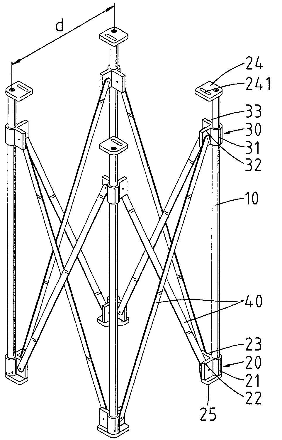
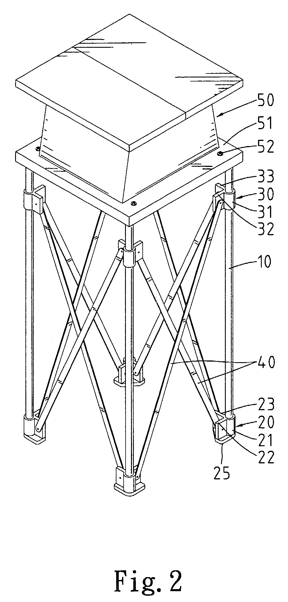
[0020] Referring to FIGS. 1-8, according to the present invention, a collapsible support for benches includes at least three legs and, more particularly, four legs in these figures.

[0021] Referring to FIGS. 1-6, according to a first embodiment of the present invention, a collapsible support includes four legs 10 on each of which a lower joint 20 and an upper joint 30 are mounted.

[0022] Each of the lower joints 20 includes a sleeve 21 for receiving one of the legs 10, two tabs 22 and 23 extending from the sleeve 21 and a foot 25 formed beneath the sleeve 21 and the tabs 22 and 23. The angle between the tabs 22 and 23 is determined based on the number of legs 10. If a collapsible support includes four legs 10, the angle between the tabs 22 and 23 is ninety degrees. If a collapsible support includes three legs 10, the angle between the tabs 22 and 23 is sixty degrees.

[0023] Each of the upper joints 30 includes a sleeve 31 for receiving one of the legs 10 and two tabs 32 and 33 extendin...


PUM


Abstract

A collapsible support includes at least three legs and a corresponding number of collapsible X-shaped structures each connected between adjacent two of the legs. Each of the collapsible X-shaped structures includes two connectors each having a lower end connected with one of the legs and an upper end connected with another one of the legs. Each of the X-shaped structures includes two lower joints connected between one of the legs and the lower end of one of the connectors and two upper joint connected between one of the legs and the upper end of one of the connectors. Each of the lower joints includes a sleeve for receiving one of the legs and a tab formed on the sleeve and connected with the lower end of one of the connectors. The lower joint includes a foot attached to the lower end of each of the legs. Each of the upper joints includes a sleeve for receiving one of the legs and a tab formed on the sleeve and connected with the upper end of one of the connectors. Each of the connectors is a strip or a tube. The support includes a number of stages each secured to an upper end of one of the legs. Each of the stages defines a slot for receiving a threaded bolt extending from a workbench.

Description

BACKGROUND OF INVENTION[0001] 1. Field of Invention[0002] The present invention relates to workbenches and, more particularly, to a collapsible support for workbenches with different sizes.[0003] 2. Related Prior Art[0004] Referring to FIG. 9, two conventional workbenches 5 and 6 are shown. The workbench 5 is mounted on a support 1 including four legs 3. The workbench 6 is mounted on a support 2 including four legs 4. The area of the workbench 5 is smaller than the area of the workbench 6. Accordingly, the distance between two adjacent legs 3 is shorter than the distance between two adjacent legs 4. The legs 3 are longer than the legs 4. The supports 1 and 2 both include a rigid configuration and a constant size. Therefore, each of the supports 1 and 2 is only suitable for supporting a workbench. When two workbenches with different sizes are needed, two supports must be carried. It is troublesome to carry two supports. Even when only one workbench is needed, it is still troublesome ...

Claims


Application Information

Patent Timeline
Patent Type & Authority Applications(United States)
IPC IPC(8): B25H1/04B25H1/12B25H1/14F16M11/00
CPCB25H1/04B25H1/12F16M2200/061F16M11/00F16M11/22B25H1/14
Inventor CHANG, LEE-CHENG
Owner JOINERY INDAL
Why Eureka
Try Eureka