Monitoring stability of an on-frequency repeater

a technology of on-frequency repeaters and stability monitoring, which is applied in the field of monitoring stability of on-frequency repeaters, can solve the problems of serious degrading of the quality of desired rf signals, part of this delay is inherent, and achieve the effect of monitoring stability and estimating the stability of the repeater

Inactive Publication Date: 2004-05-20
SPOTWAVE WIRELESS INC
View PDF12 Cites 29 Cited by
  • Summary
  • Abstract
  • Description
  • Claims
  • Application Information

AI Technical Summary

Benefits of technology

0024] An object of the present invention is to provide a method and system for monitoring stability of an on-frequency repeater.
0025] Accordingly, an aspect of the present invention provides a method of monitoring stability of an on-frequency repeater. According to the invention, a signature signal comprising a sequential series of signal pulses is generated. Each signal pulse has a selected pulse function and duration. The signature signal is transmitted through an output of the repeater. During a quiescent period between transmission of successive signal pulses, a respective quiescent power level of an input signal component received through an input of the repeater, and having a frequency corresponding to the selected pulse function, is detected. During transmission of the next successive signal pulse, a respective transmit power level of the input signal component is detected. The transmitted signature signal, and the detected quiescent and transmit power levels of the input signal component are then used to estimate stability of the repeater.
0026] Thus the present invention utilizes a pulsed signature signal, which is detected in the input signal Si during both the transmission of signal pulses and the quiescent period between pulses. This arrangement enables the signal components corresponding to the signature signal appearing in the input signal (Si) (via the leakage path) to be positively distinguished from ambient noise having the same frequency as the signature signal. By transmitting the signature signal as a low-level amplitude modulation of the output signal (So), continuous, real-time monitoring of stability can be obtained without interfering with desired communications signal traffic. Information of the system stability can be used in various ways, such as for example, to control system gain.

Problems solved by technology

For example, within a building, or a built-up urban area, signal attenuation, shadowing by buildings and / or hills; noise generated by various radio frequency sources, and multi-path effects can seriously degrade the quality of desired RF signals.
Part of this delay is inherent to the amplification process, but is primarily caused by band-pass filters used in the repeater to prevent the unwanted amplification of signals outside the frequency band of interest.
A limitation of on-frequency repeaters is that the output signal (So) can feed back to the repeater input via a so-called "leakage path".
However, if the system gain (G) becomes too high, so that Sf.gtoreq.Se, then signal leakage between the output and input antennas will cause system oscillation.
However, in practice, antenna isolation is difficult to predict, and will frequently change over time.
This system is designed to handle a single communication signal with narrowband analog voice modulation, and thus is not suitable for use with broadband signal traffic carrying multiple parallel communication signals.
However, it suffers the limitation that the tag must be located in a side-band (i.e., lying above or below the bandwidth of the desired communications signal traffic) in order to avoid interference corrupting the desired communications signal traffic and / or interfering with other network components.
This necessarily requires interruption of the communications signal traffic, which is highly undesirable.
The systems of U.S. Pat. Nos. 4,383,331 and 5,835,848 suffer the further disadvantage that, in most cases, the power level of the received test (pilot or tag) signal will be very low, requiring highly sensitive detection circuitry to successfully monitor.
However, this high sensitivity renders the detection circuit vulnerable to radio frequency interference (RFI) emitted by many common electronic devices and / or test signals transmitted by other repeaters.
The presence of noise at the same frequency as the test signal can easily render the system incapable of accurately detecting antenna isolation, and in fact may disable the repeater entirely.
However, accurate correlation between the received signal and the bit-sequence is computationally intensive.

Method used


Image

  • Monitoring stability of an on-frequency repeater
  • Monitoring stability of an on-frequency repeater
  • Monitoring stability of an on-frequency repeater

Examples


Embodiment Construction

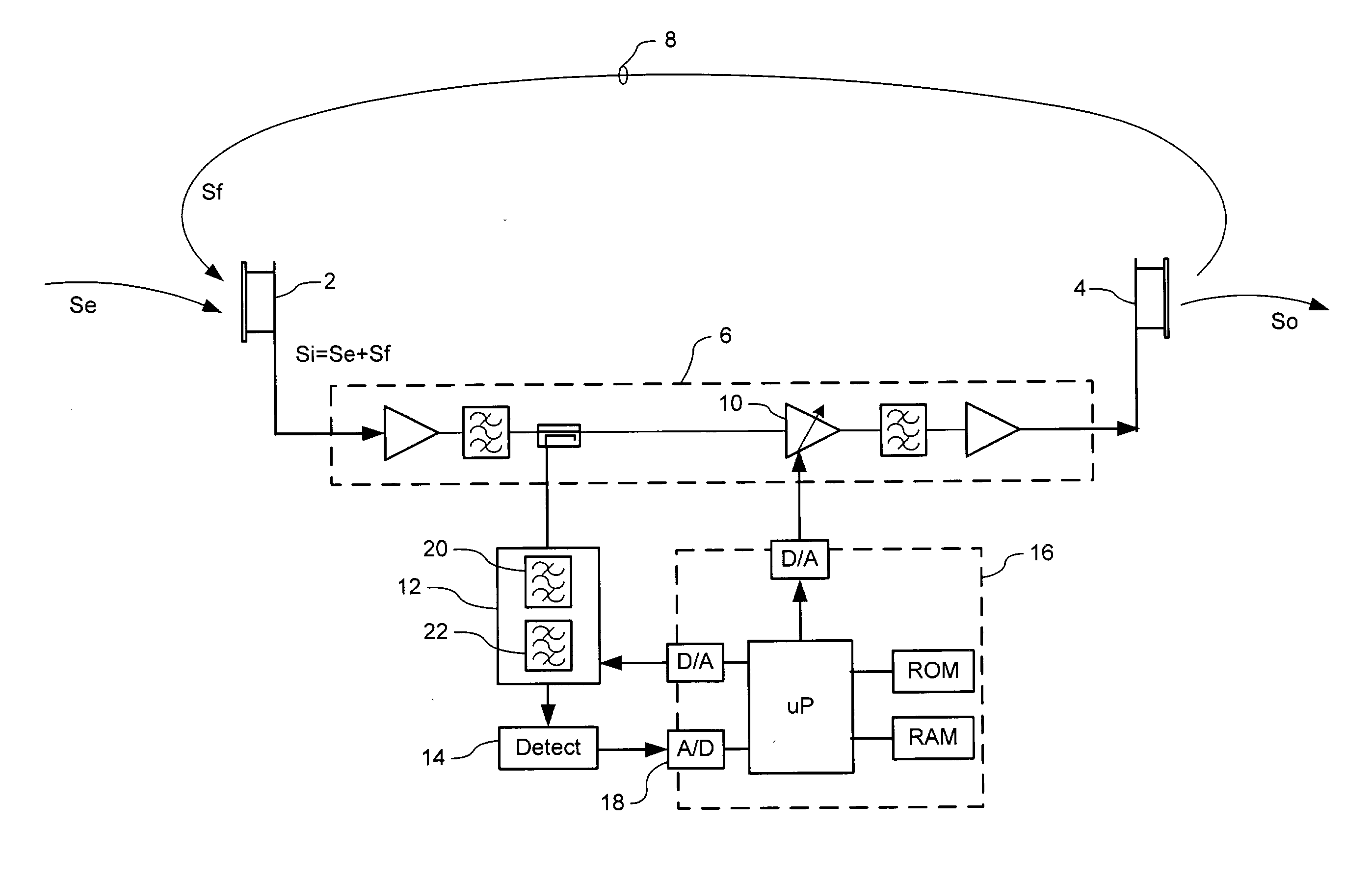
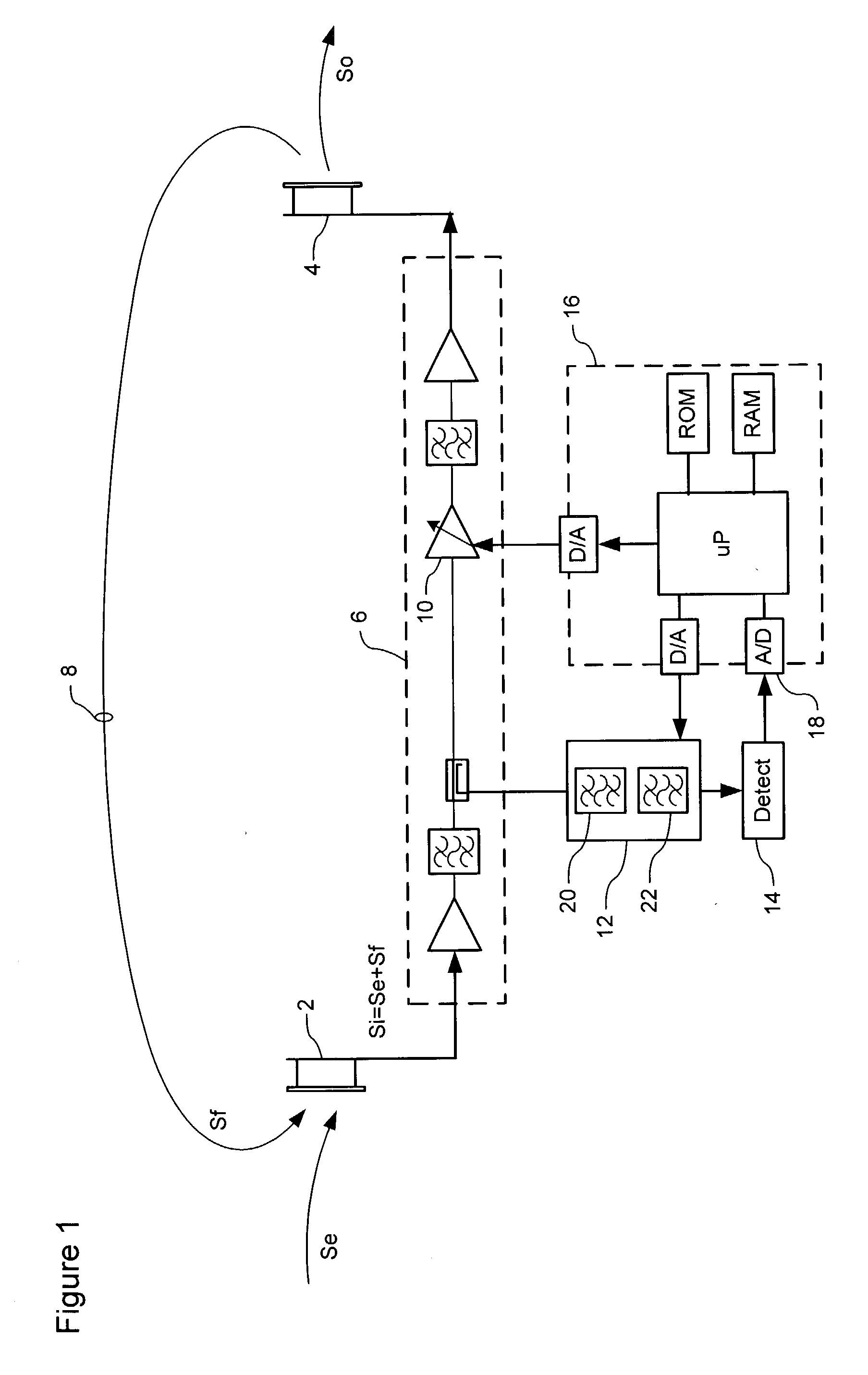
[0032] The present invention provides a method and system for monitoring stability of an on-frequency repeater. FIG. 1 is a block illustrating principle elements of an exemplary system in accordance with an embodiment of the present invention.

[0033] As shown in FIG. 1, an on-frequency repeater includes an input 2 for receiving an input signal (Si); an output 4 for radiating an output signal (So); and a signal path 6 coupled between the input 2 and output 4 in order to amplify the received input signal (Si) for retransmission as the output signal (So). If desired, the signal path 6 may include an Intermediate Frequency (IF) section (not shown) to facilitate filtering, amplification, and other signal processing functions.

[0034] FIG. 1 shows a single RF signal path 6 coupled between the input 2 and output 4, both of which are provided by respective antennas. This arrangement will clearly be suitable for unidirectional RF signal traffic. Bi-directional signal traffic through the repeate...


PUM


Abstract

A system provides evaluation of stability of an on-frequency repeater. A unique signature is imposed on RF signals transmitted by the repeater, and RF signals received by the repeater are analyzed to detect signal components corresponding to the signature. The signature signal is composed of a sequential series of signal pulses separated by a quiescent period. Respective transmit and quiescent power levels of signal components of the input signal received by the repeater are detected. These power levels are then used to estimate the system stability.

Description

CROSS-REFERENCE TO RELATED APPLICATIONS[0001] This application is the first application filed for the present invention.MICROFICHE APPENDIX[0002] Not Applicable.TECHNICAL FIELD[0003] The present application relates to wireless access networks and, in particular, to a method and system for monitoring stability of an on-frequency repeater.BACKGROUND OF THE INVENTION[0004] On-frequency repeaters are known in the art, for amplifying an input signal without otherwise altering its frequency spectrum. In some cases, an on-frequency repeater may also employ various types of active circuitry in order to enhance the signal-to-noise (S / N) ratio, in addition to simply increasing the power level. A typical application of on-frequency repeaters is for improving wireless services within defined regions of a wireless network, where signal levels would otherwise be too low for satisfactory quality of service. For example, within a building, or a built-up urban area, signal attenuation, shadowing by ...

Claims


Application Information

Patent Timeline
Patent Type & Authority Applications(United States)
IPC IPC(8): H04B7/155H04B17/40
CPCH04B7/15578H04B7/15535
Inventor BALABERDA, RANDY
Owner SPOTWAVE WIRELESS INC
Why Eureka
Try Eureka