
Electronic stethoscope measurement system and method

a technology of electronic stethoscope and measurement system, which is applied in the field of electronic stethoscope measurement system and method, can solve the problems of significant training, difficult procedure for auscultation of the heart, and the situation only tends to worsen with the increase of the listener's ag

Inactive Publication Date: 2004-06-03
3M INNOVATIVE PROPERTIES CO
View PDF6 Cites 113 Cited by
  • Summary
  • Abstract
  • Description
  • Claims
  • Application Information

AI Technical Summary

Benefits of technology

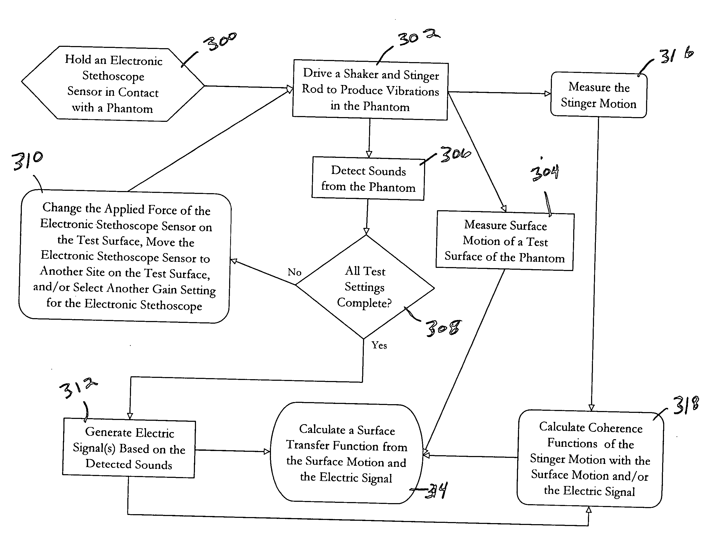
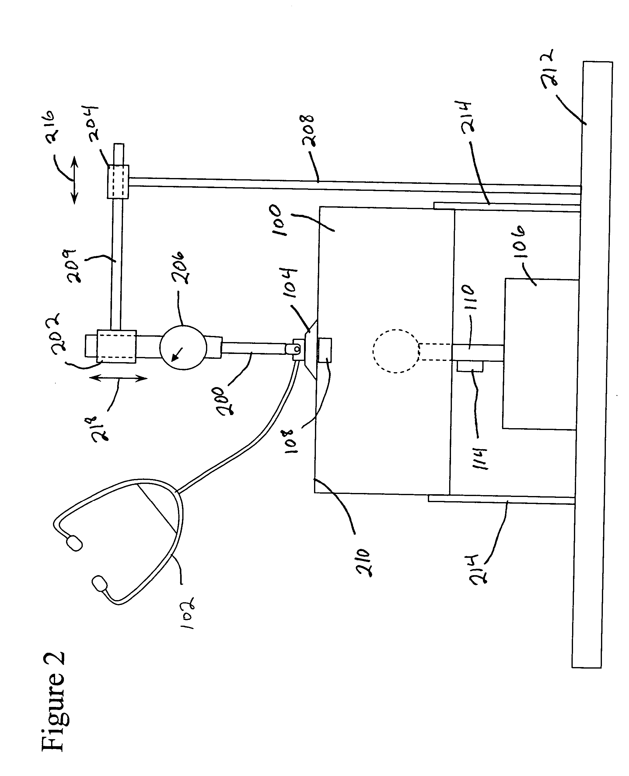
0009] An exemplary embodiment of the present invention is a method for characterizing the response of an electronic stethoscope. The sensor of the electronic stethoscope is held in contact with a test surface of a phantom body (hereinafter referred to as a phantom). A shaker, which is coupled to a stinger rod that extends inside the phantom, is driven to produce internal vibrations in the phantom. Surface moti

Problems solved by technology

Auscultation of the heart is a difficult procedure, involving significant training.
A significant portion of the signal energy in heart sounds is at frequencies below the frequency range of human hearing, and this situation only tends to worsen with increased age of the listener.
Thus, as a physician's auscultatory skill increases, his hearing may still limit his ability.
Also, auscultation relies on determining the correct sequence of brief events that are closely spaced in time, a determination that may be difficult for human listeners.
This becomes more difficult when the systolic and diastolic intervals are more equal, which typically occurs at elevated heart rates.
Learning auscultation is complicated by the reliance of diagnostic instructional manuals that rely on subjective descriptions of heart sounds, which require much practice to appreciate.
Consequently, serious heart murmurs in many patients may go undetected by physicians relying on standard auscultation technique.
This decline in auscultation skills has led to an over-reliance on echocardiography, resulting in a large number of unnecessary and expensive diagnostic studies.

Method used


Image

  • Electronic stethoscope measurement system and method
  • Electronic stethoscope measurement system and method
  • Electronic stethoscope measurement system and method

Examples


Embodiment Construction

[0016] The present invention involves a system and method for testing electronic stethoscopes. The various operating characteristics of an electronic stethoscope determined in this testing may be useful to properly analyze heart, or other bodily, sounds detected by the electronic stethoscope as part of an automated auscultatory diagnostic support system. Of particular interest is the transfer function of the electronic stethoscope. The electronic stethoscope's transfer function represents the amplitude of the output electric signal of the electronic stethoscope versus the amplitude of surface oscillations of the body on which the auscultation is being performed, as a function of frequency. This transfer function may be used to more accurately relate the electric output signals to the actual sounds detected during auscultation procedure and, thus, allow a more certain analysis of these sounds.

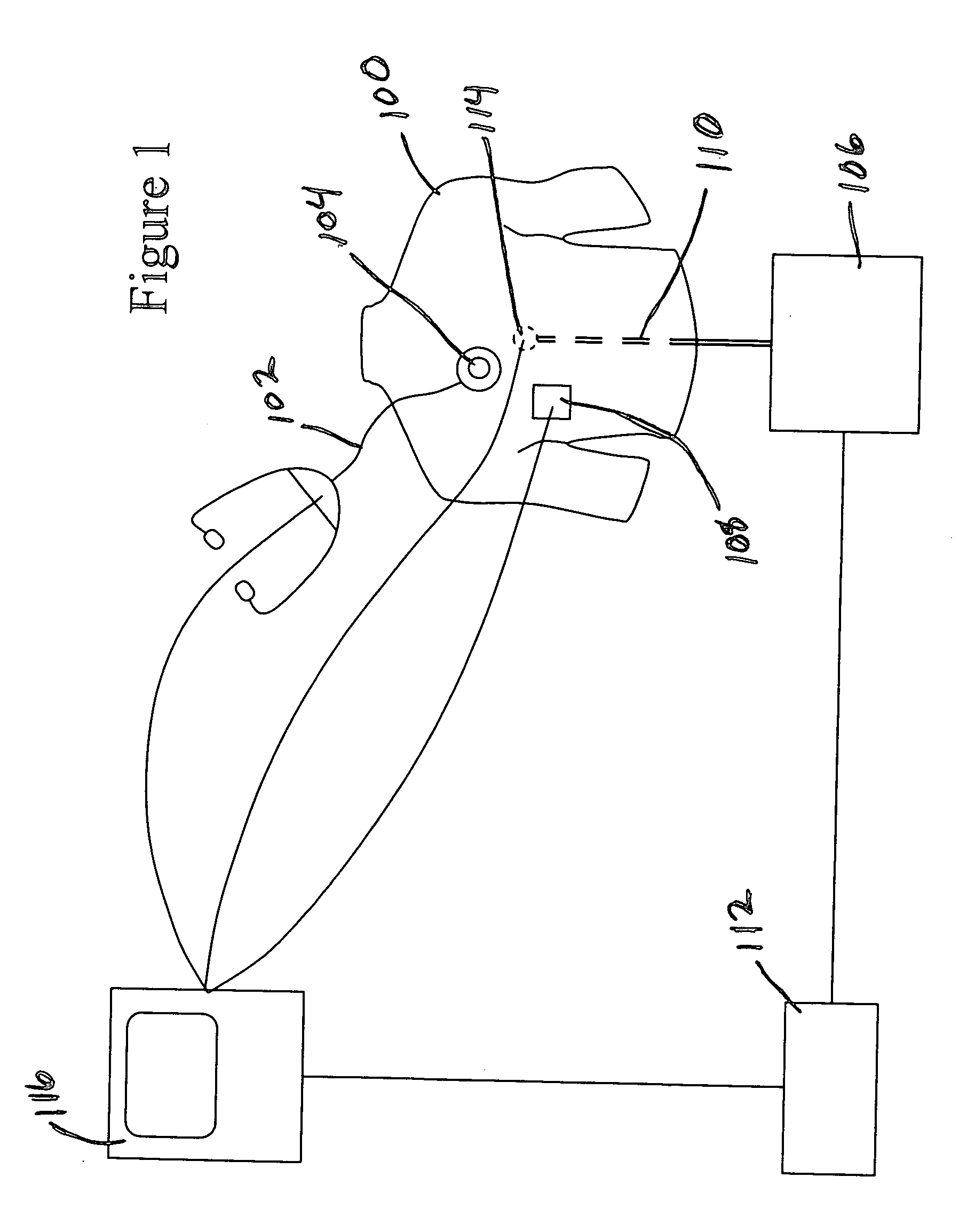
[0017] FIG. 1 is a block diagram that shows an exemplary embodiment of the present invention...


PUM


Abstract

A method and apparatus for characterizing the response of an electronic stethoscope. The sensor of the electronic stethoscope is held in contact with a test surface of a phantom. A shaker, which is coupled to a stinger rod that extends inside the phantom, is driven to produce internal vibrations in the phantom. Surface motion of the test surface of the phantom is measured using a surface accelerometer coupled to the test surface. Vibrations from the phantom are detected and an electric signal based on the detected vibrations is generated with the electronic stethoscope. A surface transfer function is calculated based on the measured surface motion and the electric signal to characterize the response of the electronic stethoscope.

Description

[0001] This application is related to and claims the benefit of U.S. Provisional Application No. 60 / 427,160 entitled A PROPOSAL FOR STETHOSCOPE MEASUREMENT SYSTEM FOR ZARGIS MEDICAL CORPORATION filed on Nov. 18, 2002.FIELD OF THE INVENTION[0002] The present invention relates to the field of systems and methods for characterizing electronic stethoscopes, specifically with respect to sounds within the thorax of a subject.BACKGROUND OF THE INVENTION[0003] Auscultation of the heart is a well-defined and standard component of the physical examinations of patients. It is typically performed with a commercially available stethoscope. Physicians perform auscultation by listening to heart sounds desirably, in sequence, at a set of well-defined sites on the chest surfaces. These sites are typically defined with reference to anatomical landmarks, such as the second intercostal space on the left, etc. They may also be defined based on the heart valve preferentially heard at that location (i.e.,...

Claims


Application Information

Patent Timeline
IPC IPC(8): A61B7/04
CPCA61B7/04
Inventor GROVE, DEBORAH M.
Owner 3M INNOVATIVE PROPERTIES CO
Learn More