Internal broach

a broach and internal technology, applied in the field of internal broaches, can solve the problems of insufficient profile accuracy and flank surface quality, negative influence of flank curve accuracy, and considerable drawbacks

Inactive Publication Date: 2004-06-10
FORST TECH
View PDF13 Cites 9 Cited by
  • Summary
  • Abstract
  • Description
  • Claims
  • Application Information

AI Technical Summary

Problems solved by technology

Very often, profile accuracy and flank surface quality are not sufficient in this case, flank curve accuracy being satisfactory as a rule.
This is due to the fact that the relief-ground flank cutting blades of the sizing teeth are sharp cutting edges of comparatively bad self-guidance behavior.
It is inherent in the system that any changeover from a progressively stepped broaching operation to full form sizing is accompanied with a break in the broaching force, which leads to considerable drawbacks, in particular in the case of twist broaching.
This change may be sufficiently strong so that the full form sizing section is not led correctly into the progressively broached profiles and, as a result, machines the flanks unilaterally so that the profile is not sized on both flanks.
Owing to the mentioned deficiencies of the profile produced by progressively stepped broaching, the flank cutting blades of the broach cutting teeth will cut irregularly into the stepped flanks of the profile, with torsional vibrations originating which may negatively affect flank curve accuracy.
In the case of great height of the profiles that are to be produced, this will lead to wide spacings of teeth, which has the consequence that, with a given number of broach cutting teeth, the broach becomes too long.
If however the spacing of teeth is reduced in spite of too great a height of the profile that is to be produced, this may lead to grinding problems.
However, the problem of broach deviation i.e., the problem of the central longitudinal axis of the broach deviating from its desired position relative to the work piece, cannot be solved in a satisfying fashion.

Method used


Image

  • Internal broach
  • Internal broach
  • Internal broach

Examples


Embodiment Construction

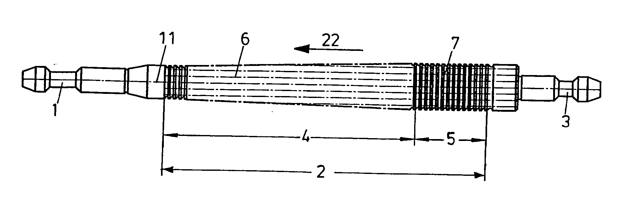
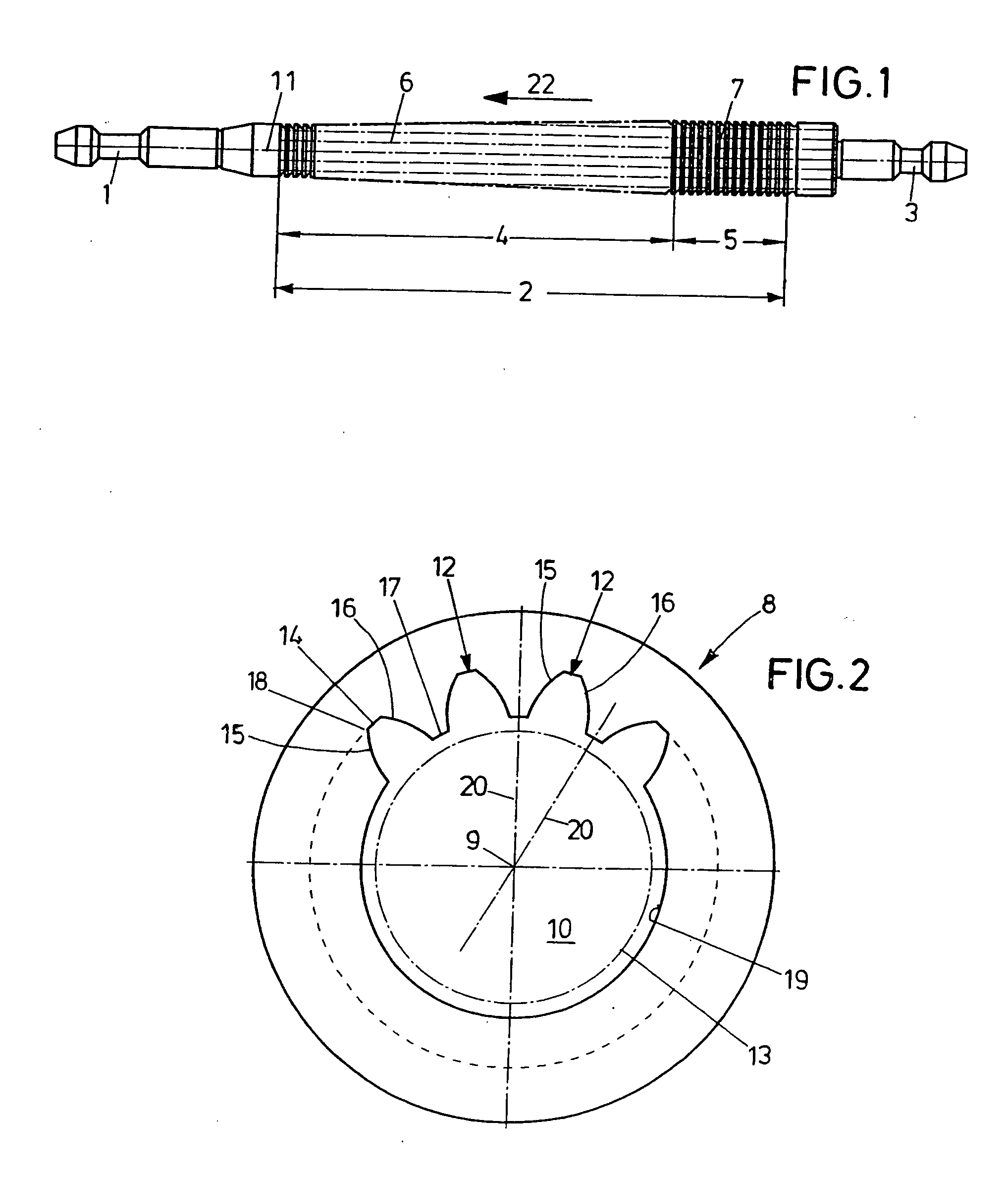
[0030] The internal broach seen in FIG. 1, the fundamental structure of which is familiar, comprises a shank 1, a toothed section 2 and a tail end 3 subsequent thereto. The toothed section 2 includes a broaching portion 4 subsequent to the shank 1 and an adjoining sizing portion 5 upstream of the tail end 3. The broaching portion 4 has several rows 6 of broach cutting teeth that will be explained below. The sizing portion 5 also includes a number of rows 7 of sizing teeth.

[0031] The broach serves to machine for instance an annular work piece 8 which is illustrated in FIG. 2. Prior to being broached, it has a borehole 10 concentric of the central longitudinal axis 9 of the finished work piece 8. The work piece 8 is placed on a work piece support of an internal broaching machine; then the shank 1 of the broach is led through the borehole 10 and seized by a puller of the broaching machine, the puller being drivable in the direction of the axis 11 of the broach, drawing the broach throu...


PUM

PropertyMeasurementUnit
thicknessaaaaaaaaaa
depthaaaaaaaaaa
widthaaaaaaaaaa

Abstract

An internal broach for internally broaching profiles, defined by a bottom and flanks, of female serrations of a work piece comprises a toothed section with several rows of broach cutting teeth, the rows being disposed successively counter to a direction of broaching, with successive broach cutting teeth being allocated to each other for broaching a profile. The broach cutting teeth have bottom cutting blades and first and second sides. The first sides are guide flanks, the edges of which are guide edges without cutting ability. The second sides are relieved flanks, the edges of which are relieved edges without cutting ability.

Description

[0001] 1. Field of the Invention[0002] The invention relates to an internal broach for internally broaching profiles defined by a bottom and flanks, in particular female serrations, in a work piece, comprising a shank, which leads in a direction of broaching and has a central longitudinal axis; and a toothed section with several rows of broach cutting teeth, the rows being disposed successively counter to the direction of broaching; with successive broach cutting teeth being allocated to each other for broaching a profile of a depth; with the broach cutting teeth having bottom cutting blades and first and second sides; with the bottom cutting blades of successive and associated broach cutting teeth having a pitch a relative to the broach cutting teeth that lead in the direction of broaching; with a bottom-cutting-blade relief surface being allocated to the bottom cutting blades; and with the first and second sides passing through the bottom-cutting-blade relief surfaces while formin...

Claims


Application Information

Patent Timeline
Patent Type & Authority Applications(United States)
IPC IPC(8): B23D43/02B23F21/26
CPCB23D43/02B23F21/26Y10T407/1671Y10T407/1685Y10T407/16
Inventor WEGHAUS, NORBERTPFITZER, OTTOBERKTOLD, ANDREAS
Owner FORST TECH
Why Eureka
Try Eureka