Gasket

a gasket and valve body technology, applied in the direction of hose connection, cable termination, mechanical equipment, etc., can solve the problems of numerous stresses on the corrugated pipe used for ground water drainage, and achieve the effect of facilitating frictional engagement of the bell

Inactive Publication Date: 2004-08-05
ADVANCED DRAINAGE SYST
View PDF70 Cites 30 Cited by
  • Summary
  • Abstract
  • Description
  • Claims
  • Application Information

AI Technical Summary

Benefits of technology

0008] In accordance with the invention, the gasket further comprises a sealing portion integrally molded with the seating portion including first and second shoulder portions and an arcuate sealing surface extending between the first and second shoulder portions in radially opposed relation to the seating portion. The first shoulder portion extends from the seating portion and is disposed to engage the surface of the male end or spigot adjacent one side of the annular recess, and the second shoulder portion extends in the opposite direction from the seating portion a distance greater than the first shoulder porti

Problems solved by technology

Unlike many piping systems, corrugated pipe used for ground water drainage is subjected to numerous stresses

Method used


Image

  • Gasket
  • Gasket
  • Gasket

Examples


Embodiment Construction

[0020] Reference will now be made in detail to the presently preferred embodiments of the invention, examples of which are illustrated in the accompanying drawings.

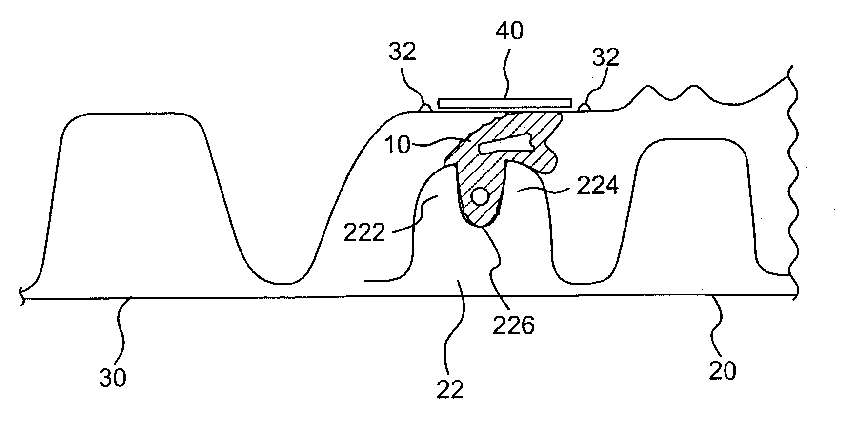
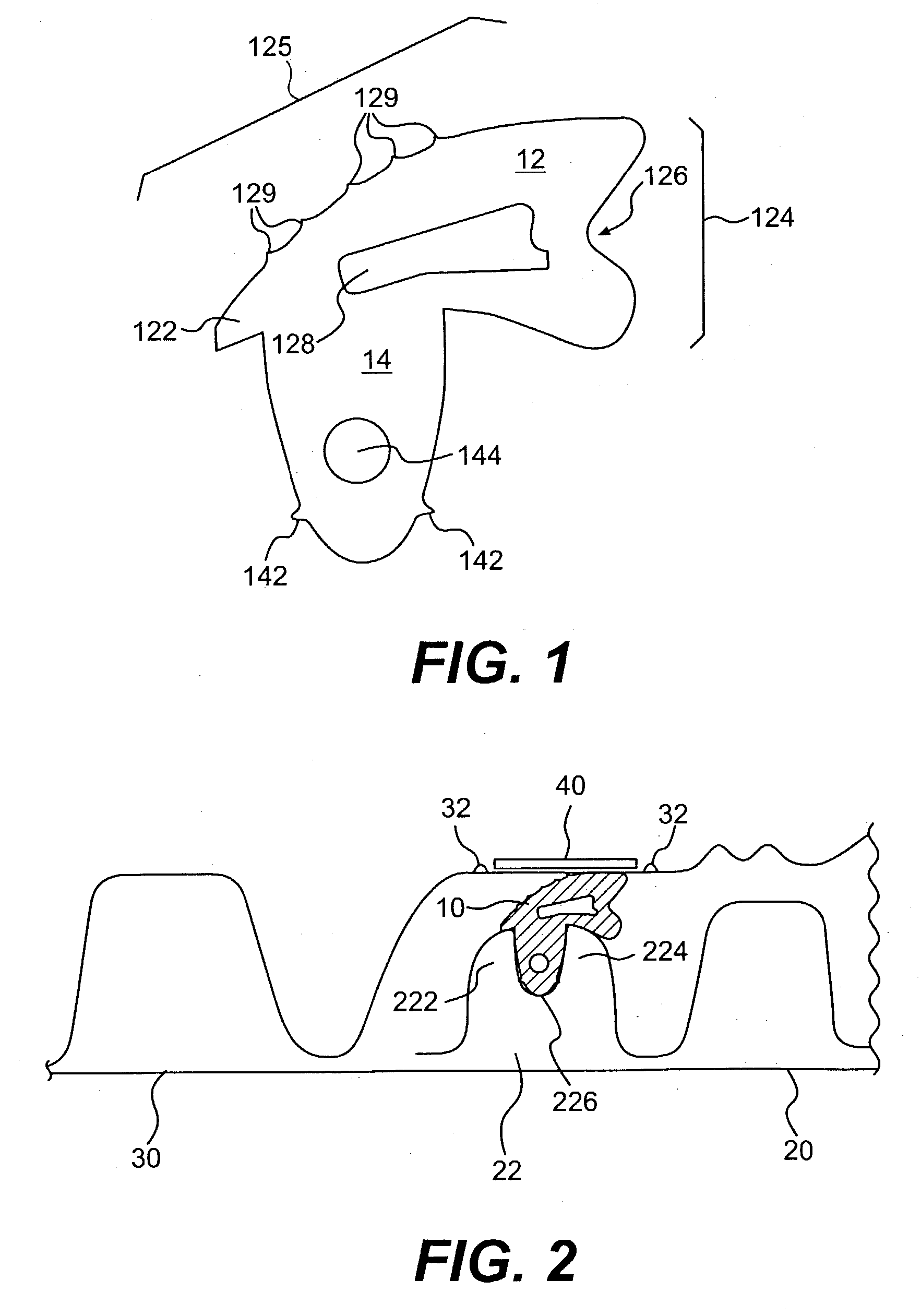
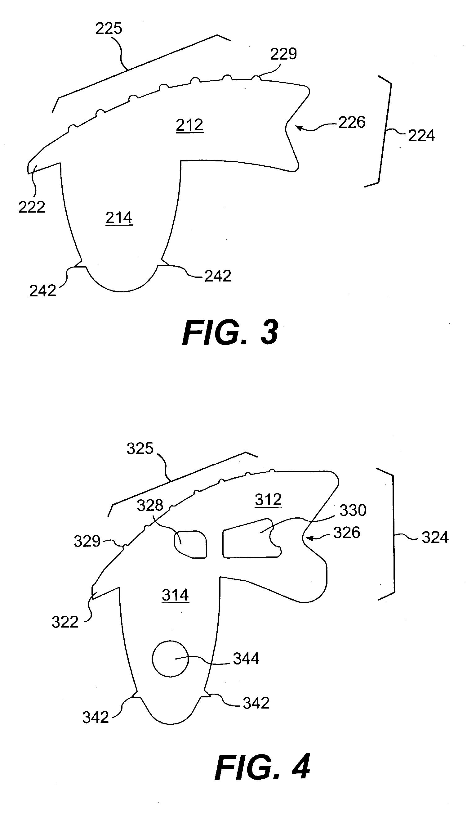
[0021] As shown in FIG. 1, an embodiment of the gasket of the present invention is an integral unit that includes a sealing portion 12 and a seating portion 14. The seating portion 14 is preferably shaped to fit within a recess of a mini-corrugation of a pipe (see FIG. 2) or in a recess between corrugations of a pipe (not shown). The seating portion 14 may optionally include at least one annularly-extending ridge 142 that improves gripping of the seating portion within the recess and fills longitudinal die lines and minor imperfections in the recess' sealing surface. The seating portion may additionally include a cavity 144 that allows the gasket to adjust to forces that it may be subjected to during use.

[0022] The sealing portion 12 preferably includes a downstream shoulder 122 and an upstream shoulder 124. An arcuate su...


PUM


Abstract

An annular gasket for affecting a watertight seal between two sections of corrugated pipe. The gasket comprises a seating portion dimensioned to fit within an annular recess in one of the mated sections of corrugated pipe, and a sealing portion integrally molded with the seating portion. The sealing portion includes a first shoulder portion, a second shoulder portion, and an arcuate surface extending between the first and second shoulder portions. The mass of the seating portion is less than the mass of the sealing portion.

Description

I. BACKGROUND OF THE INVENTION[0001] It is well known to use an annular gasket between mated male and female pipe end sections to form a fluid-tight seal. In most applications, the annular elastomeric gasket is disposed around the end of the male pipe section. In many applications, the gasket is seated in an annular groove that extends around the end of the male pipe section. See, for example, U.S. patent application Ser. No. 10 / 037,219, for a PIPE HAVING WATERTIGHT INLINE BELL, filed Nov. 9, 2001.[0002] In ground water drainage systems, corrugated pipe of various diameters are used. Sections of such pipe are joined by mating a female end or bell, and a male end or spigot. As with any fluid conveyance piping system, proper sealing at the joined ends is necessary. Unlike many piping systems, corrugated pipe used for ground water drainage is subjected to numerous stresses during installation and use that must be accommodated by any annular gasket disposed between bell and spigot.[0003...

Claims


Application Information

Patent Timeline
IPC IPC(8): F16L21/03
CPCF16L21/03F16L25/0054
Inventor SHAFFER, WILLIAM V.ANDRICK, WILLIAM C.
Owner ADVANCED DRAINAGE SYST
Why Eureka
Try Eureka