Bezel assembly for pneumatic control

a pneumatic control and bezel technology, applied in the direction of positive displacement liquid engines, liquid fuel engines, instruments, etc., can solve the problems of blood transfusions with associated risks, microorganisms capable of causing disease (i.e., pathogens) could pass from the donor blood, and the shelf life of diluted anti-pathogen compounds is very short, so as to reduce the pump stroke

Active Publication Date: 2005-05-05
DEKA PROD LLP
View PDF99 Cites 147 Cited by
  • Summary
  • Abstract
  • Description
  • Claims
  • Application Information

AI Technical Summary

Benefits of technology

[0014] The elevated contour limits the movement of the gasket into the depression thus reducing the pump stroke. The elevated contour may be in the shape of a mound that increases in height from a perimeter of the depression toward a higher middle of the m

Problems solved by technology

Although helpful in many cases, blood transfusions have associated risks.
Among others, there is a risk that microorganisms capable of causing disease (i.e., pathogens) could pass from the donor blood to the ultimate blood recipient.
One complexity with this process, however, is the fact that the diluted anti-pathogen compound has a very short shelf life (e.g., on the order of about four hours).
The anti-pathogen compound is not easy to handle before it is diluted.
To the contrary, it has a very high pH (e.g., on the order of 11.0 or higher) and thus, is highly caustic and toxic.
Mere contact with the undiluted solutio

Method used


Image

  • Bezel assembly for pneumatic control
  • Bezel assembly for pneumatic control
  • Bezel assembly for pneumatic control

Examples


Embodiment Construction

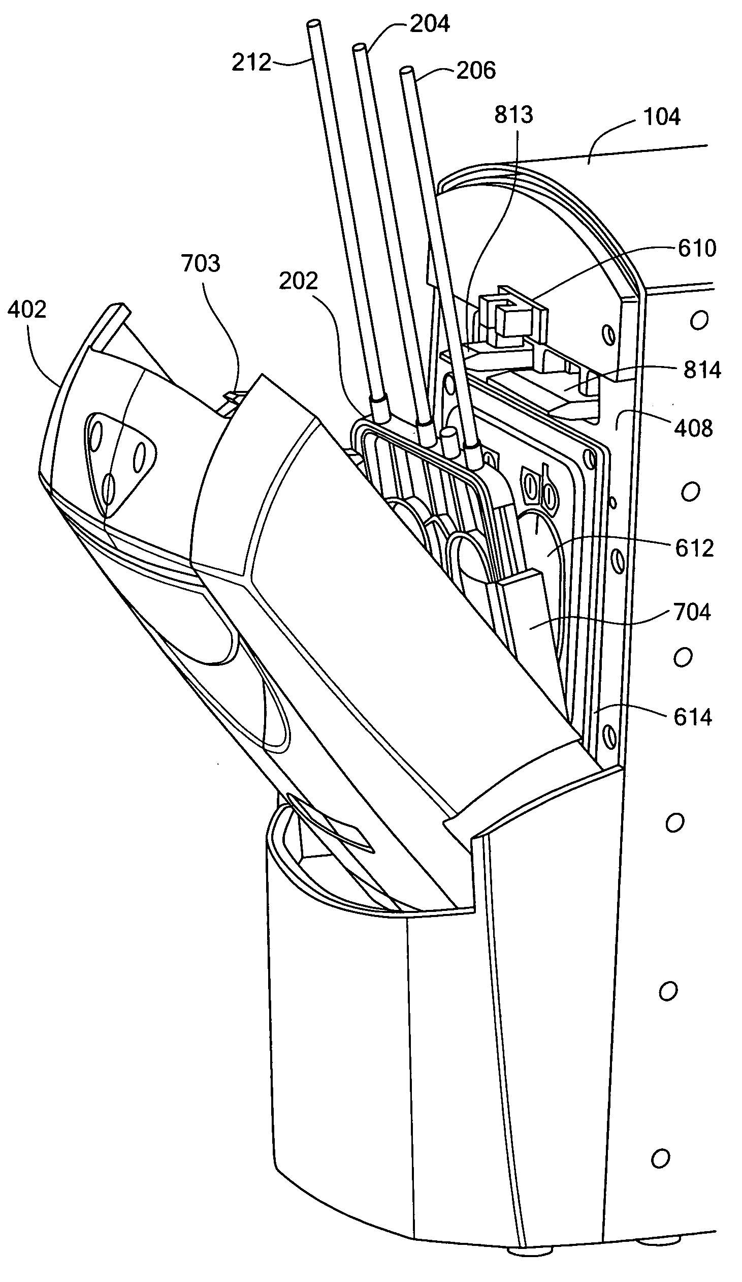
[0046] In order to mix two liquids, a first liquid is pumped into a first pump chamber of a pumping apparatus through a channel of the pumping apparatus. A second liquid is pumped from a second pump chamber of the pumping apparatus into either the channel or the first pump chamber, preferably while the first liquid is being pumped into the first pump chamber. In this way, the two liquids are mixed within the pumping apparatus, and, more specifically, within the channel and / or the first pump chamber of the pumping apparatus. The second liquid is preferably pumped in a pulsatile mode in which small quantities of the second liquid are pumped at intervals. The quantity and / or the interval can be dynamically adjusted to result in a predetermined concentration of the two liquids. The contents of the first pump chamber are pumped to a receptacle.

[0047] The pumping apparatus may be a disposable pump cassette. The pump cassette typically includes two pump chambers and various valves. The pu...


PUM

PropertyMeasurementUnit
Pressureaaaaaaaaaa
Diameteraaaaaaaaaa
Sizeaaaaaaaaaa

Abstract

A bezel and bezel assembly in which the bezel is a rigid block with a plurality of cavities. A depression in the block has ribs extending up therefrom to form an elevated contour. The depression includes at least one cavity therein for the application of air pressure into the depression and over the elevated contour. A gasket fits over the bezel so that positive pressure applied through the at least one cavity in the depression forces a gasket membrane to expand away from the pumping side and negative pressure applied through the at least one cavity in the depression pulls the gasket membrane against the elevated contour of the ribs. The bezel may include solvent bondable tubing connections for making pneumatic connections to the bezel.

Description

CROSS-REFERENCE TO RELATED APPLICATION(S) [0001] The present application may include subject matter related to one or more of the following commonly-owned United States patent applications, each of which was filed on even date herewith and is hereby incorporated herein by reference in its entirety: [0002] U.S. patent application Ser. No. ______ entitled SYSTEM, DEVICE, AND METHOD FOR MIXING A SUBSTANCE WITH A LIQUID (referred to herein as “Application D70”); [0003] U.S. patent application Ser. No. ______ entitled SYSTEM, DEVICE, AND METHOD FOR MIXING LIQUIDS (referred to herein as “Application D71”); [0004] U.S. patent application Ser. No. ______ entitled TWO-STAGE MIXING SYSTEM, APPARATUS, AND METHOD (referred to herein as “Application D72”); [0005] U.S. patent application Ser. No. ______ entitled SYSTEM AND METHOD FOR PUMPING FLUID USING A PUMP CASSETTE (referred to herein as “Application D73”); [0006] U.S. patent application Ser. No. ______ entitled DOOR LOCKING MECHANISM (referr...

Claims


Application Information

Patent Timeline
IPC IPC(8): A61L2/00A61L2/24A61M1/02A61M1/36B01F25/60F04B1/00F04B43/073F04B43/08F04B43/12F04B45/06G05D11/13
CPCA61L2/0088Y10T29/53A61M1/0272A61M1/0281A61M1/3687B01F3/0865B01F3/088B01F5/0077B01F5/12B01F13/1013B01F13/1016B01F15/0202B01F15/0475B01F2015/0221G05D11/132F04B53/16A61M1/0213A61L2/24A61M2205/125Y10T137/0352Y10T137/0329Y10T137/86131Y10T137/87652Y10T292/0911Y10T292/212Y10T292/438F04B43/06B01F23/451B01F23/49B01F25/105B01F25/60B01F33/811B01F33/81B01F35/711B01F35/715B01F35/8823Y02A50/30A61M1/36225F04B53/22F04B43/0009F04B13/02F04B23/06F04B53/06F04B23/02F04B49/22
Inventor TRACEY, BRIANMCGILL, DAVID W.
Owner DEKA PROD LLP
Why Eureka
Try Eureka