Hemostasis valve

a technology of hemostasis cannula and valve body, which is applied in the field of medical devices and instruments, can solve the problems of difficult to employ a single hemostasis valve, difficult for the valve to seal adequately against the backward pressure of blood, and excessive blood leakage,

Inactive Publication Date: 2003-04-22
ST JUDE MEDICAL ATRIAL FIBRILLATION DIV
View PDF29 Cites 159 Cited by
  • Summary
  • Abstract
  • Description
  • Claims
  • Application Information

AI Technical Summary

Problems solved by technology

However, when a guidewire is inserted through most hemostasis valves, because the guidewire is so small relative to the catheters which may also be employed, it is difficult for the valve to seal adequately against the backward pressure of blood, while at the same time permitting easy insertion of much larger diameter catheters into the vasculature.
This problem is particularly acute with catheterization procedures involving arterial invasion where there is a high reverse pressure of blood.
Excessive blood leakage may be extremely dangerous to patients and a contaminant to physicians.
It has often been difficult to employ a single hemostasis valve with catheters of widely varying diameters because adequate sealing around the catheter walls cannot be achieved.
The presence of the catheter introducer and the insertion of different size catheters often causes bleeding during cardiac catheterization procedures.
Because adequate sealing around the elongated cylindrical medical devices using conventional hemostasis valves cannot be assured for a wide variety of devices, each having a different diameter, it has not been possible to utilize a single hemostasis valve with devices of widely varying diameters.
Also, many of the prior art hemostasis valves exhibit various performance defects due to various structural features.
For example, it may be difficult to manipulate an elongated cylindrical medical device through the passageway formed by automatically closed slits because no pre-guiding centering channel is provided.
The introduction of the medical device creates an axial gap between the gaskets that may result in leakage of blood under blood pressure.
However, the insertion force necessary for insertion of medical catheters through the passageway of the valves dramatically increases because the deformation force for the two slits of the hemostasis valve is in opposition to one another and the friction at the intersecting location of the two slits inside the valves increases.
For Type III hemostasis valves, the insertion force may also be a problem.
In addition, these values often do not seal against the leakage of blood when a small-diameter guidewire passes through its slit passageway.
Further, the restitutive force created by the retraction of larger-diameter catheters may cause the seepage of air into the blood stream.

Method used


Image

  • Hemostasis valve
  • Hemostasis valve
  • Hemostasis valve

Examples


Embodiment Construction

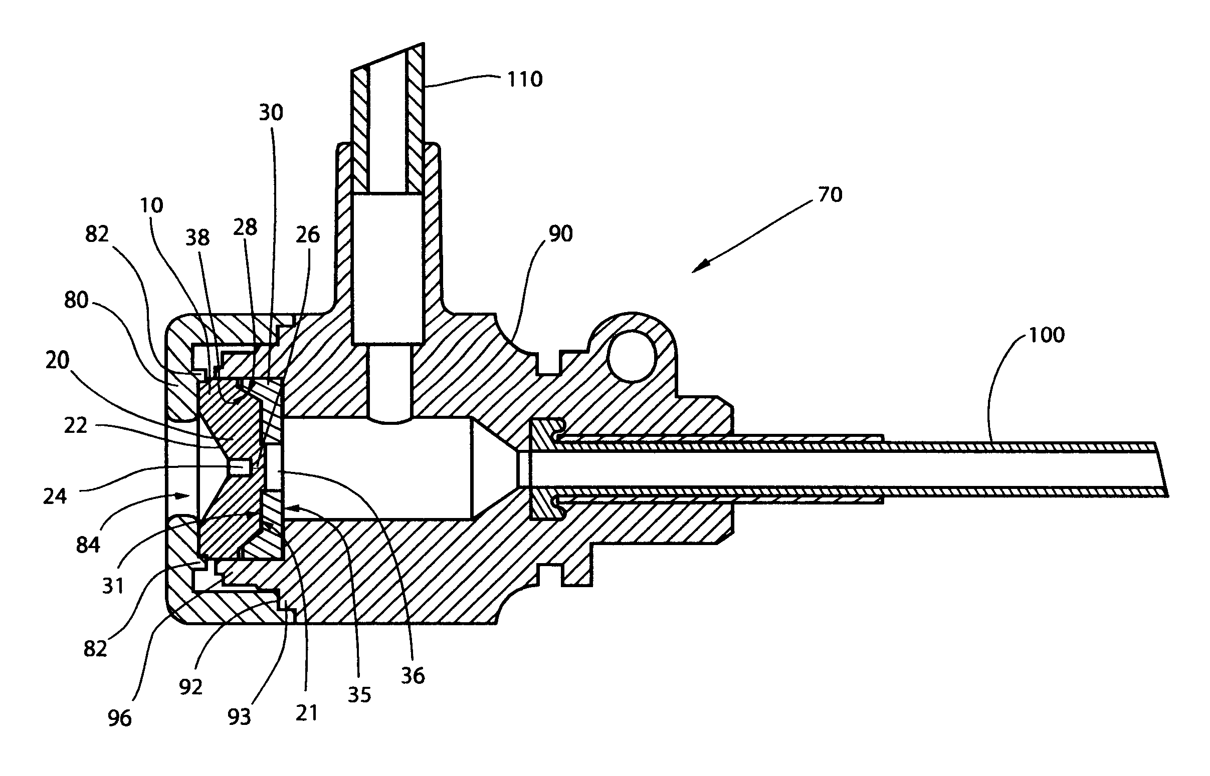
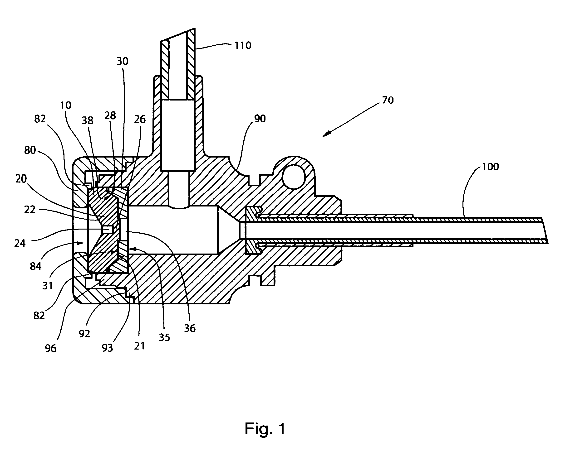
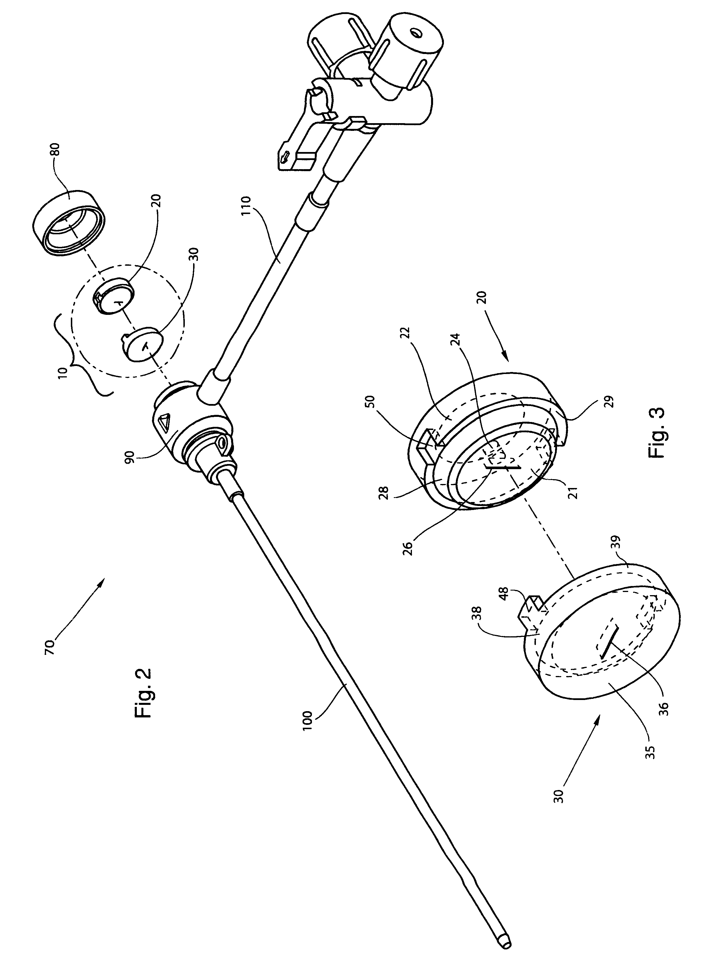
The high performance hemostasis valve (10) of the present invention is preferably incorporated in a hemostasis cannula assembly (70) used, for example, for various cardiac catheterization procedures in which a dilation catheter or treating catheter advances over a small guidewire into a blood vessel.

The hemostasis cannula assembly (70) is formed of five major components, as shown in FIGS. 1 and 2. The first of these components is the cap (80), which is attached to the proximal end of the second component--the longitudinally extended valve housing or hub (90). The valve housing (90) has a proximal and distal opposing openings through which elongated cylindrical medical devices are inserted into and out of the interior of the valve housing or hub (90). The cap (80) and valve housing (90) of the cannula assembly (70) are preferably made from a relatively rigid thermoplastic material, such as a high-density polyethylene or an acrylonitrile-butadiene-styrene copolymer. The cap (80) may b...


PUM


Abstract

A hemostasis cannula unit including a valve housing, a cap, and a hemostasis valve, wherein the hemostasis valve includes a valve gasket and a valve membrane compressed against the valve gasket by the valve housing, wherein the valve gasket is thicker than the valve membrane.

Description

None.BACKGROUND OF INVENTION1. Field of InventionThis invention relates to medical devices and instruments. More particularly, this invention relates to hemostasis valves and hemostasis cannula units containing a hemostasis valve, wherein the hemostasis valve is comprised of two separate valve members, a valve gasket and a complementarily shaped valve membrane, each of which has a different thickness.2. Prior ArtThe introduction of catheters into blood vessels for a variety of purposes such as coronary angiography has been known for many years. Several techniques for introducing these catheters into the vasculature of the human body are available. One such technique is the cut-down method, while another is the Seldinger technique. The Seldinger technique includes surgically opening a vein or artery with a needle, inserting a guidewire into the vessel through the lumen of the needle, withdrawing the needle, inserting over the guidewire a dilator which has passed through an associated...

Claims


Application Information

Patent Timeline
Patent Type & Authority Patents(United States)
IPC IPC(8): A61M39/02A61M39/06
CPCA61M39/06A61M39/0606A61M2039/0686A61M2039/064A61M2039/0653A61M2039/0633
Inventor GUO, XIAOPINGSTEHR, RICHARD
Owner ST JUDE MEDICAL ATRIAL FIBRILLATION DIV
Why Eureka
Try Eureka