Apparatus and methods to complete wellbore junctions

a technology of junctions and junctions, applied in the direction of directional drilling, drilling pipes, borehole/well accessories, etc., can solve the problems of not always necessary or even desirable to utilize a device, the insertion of the junction device is complex, and the manufacturing cost of the junction device is high

Inactive Publication Date: 2004-08-19
WEATHERFORD TECH HLDG LLC
View PDF39 Cites 65 Cited by
  • Summary
  • Abstract
  • Description
  • Claims
  • Application Information

AI Technical Summary

Benefits of technology

[0021] In a fifth embodiment, a lateral wellbore is formed from an existing, cased central wellbore after a cylindrical section of screen is disposed across a window is formed by milling the casing wall. Thereafter, as with the previous embodiments of the invention, a liner is run-in to the lateral wellbore in a manner that extends the screen material along the outer portion of the liner, causing the screen material to cover the interface between the liner and the window.

Problems solved by technology

Because of their complexity, these junction-lining devices are very expensive to manufacture and their insertion into a wellbore is complex.
More importantly, it is not always necessary or even desirable to utilize a device in a wellbore junction that prevents commingling of fluids.
For example, junctions that are left completely unlined are more likely to suffer cave in or be adversely affected by pressure spikes from one of the wellbores or from a surrounding formation.
Additionally, unlined wellbores have no means to prevent solids from entering the junction and interfering with the production of liquid hydrocarbons.
Sand production can result in premature failure of artificial lift and other downhole and surface equipment.
Particles can compact and erode surrounding formations to cause liner and casing failures.
In addition, produced sand becomes difficult to handle and dispose of at the surface.
Ultimately, open holes carry the risk of complete collapse of the formation into the wellbore.
While gravel packs inhibit the production of sand with formation fluids, they often fail and require replacement due, for example, to the deterioration of the perforated or slotted liner or screen as a result of corrosion or the like.
In addition, the initial installation of a gravel pack adds considerable expense to the cost of completing a well.
The removal and replacement of a failed gravel pack is even more costly.
The issues related to unlined junctions are most critical during the time a lateral wellbore is being drilled; long before a conventional junction support could be installed.
Thus, production from the formation at the point of the junction itself has heretofore been impossible.
In these cases, there is no reason to prevent co-mingling of the fluids between the wellbores.
Finally, there are instances when cemented junctions become brittle or are damaged by pressure differentials.

Method used


Image

  • Apparatus and methods to complete wellbore junctions
  • Apparatus and methods to complete wellbore junctions
  • Apparatus and methods to complete wellbore junctions

Examples


Embodiment Construction

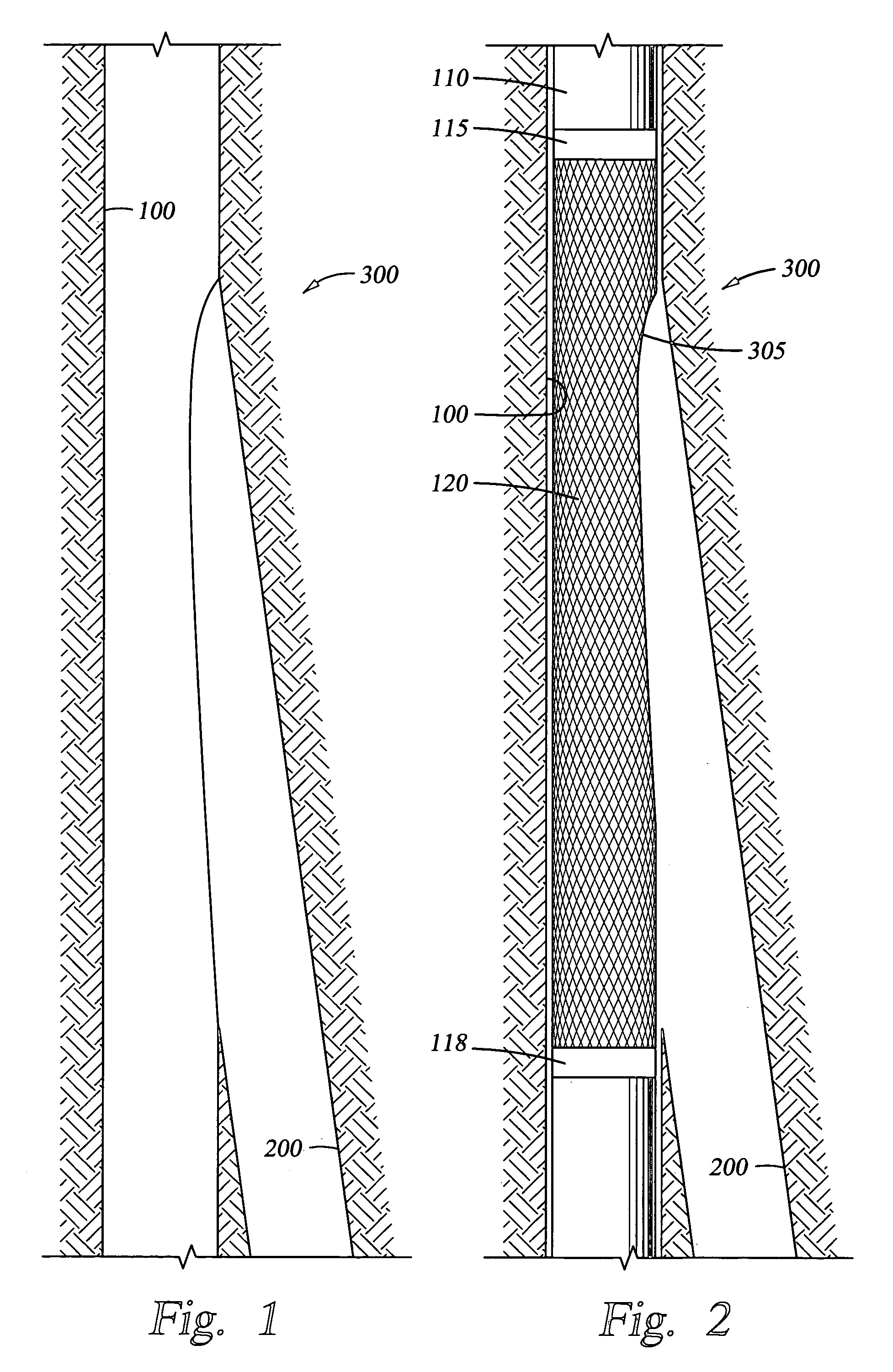
[0049] FIG. 1 is a section view showing a central wellbore 100 with a lateral wellbore 200 extending therefrom. Typically, the central wellbore 100 is formed and thereafter, using some whipstock or other diverter that is temporarily placed in the central wellbore 100, the lateral wellbore 200 is formed to more fully access a formation or to access a different formation adjacent the central wellbore 100. In this specification, the interface between the central wellbore and the lateral wellbore is considered a wellbore junction and that junction 300 is generally illustrated in FIG. 1.

[0050] FIG. 2 is a section view illustrating the wellbore 100 with a string of casing 110 disposed therein. In the case of FIG. 2, the string of casing 110 includes a section, which includes screen material 120 disposed therein and held at each end by upper and lower rings 115, 118. Preformed in a wall of the casing 110 at junction 300 is a window 305 visible in profile in FIG. 2. The purpose of the scree...


PUM


Abstract

A method and apparatus for completing a wellbore junction is provided. In one embodiment, a first leg of a screen is fastened within a first tubular with a preformed window. The first tubular houses a whipstock with a cut-out portion containing a folded second leg of the screen. The first tubular is lowered into a junction of a central and a lateral wellbore. A second tubular is lowered within the first tubular and catches an end of the folded second leg of the screen thereby unfolding and expanding the screen as the second tubular is guided into the lateral wellbore. In another embodiment, an expandable sand screen junction component with expandable sand screen production tubing is lowered through a junction of a central and lateral wellbore into the lateral wellbore and expanded into place. A central wellbore access port is milled into the junction component. Various additional methods and apparatuses for providing selective production among the central wellbore, junction, and / or lateral wellbore are provided.

Description

[0001] This application claims benefit of U.S. provisional patent application serial No. 60 / 424,455, filed Nov. 7, 2002, which is herein incorporated by reference.[0002] 1. Field of the Invention[0003] The present invention relates to methods for completing wells, such as hydrocarbon and water wells. Particularly, the present invention relates to junctions in multilateral wellbores. More particularly, the invention relates to an apparatus and methods for forming and completing junctions, especially junctions designed for solids exclusion.[0004] 2. Description of the Related Art[0005] Hydrocarbon wells are typically formed with a central wellbore that is supported by steel casing. The steel casing lines the borehole formed in the earth during the drilling process. This creates an annular area between the casing and the borehole, which is filled with cement to further support and form the wellbore.[0006] Some wells are produced by perforating the casing of the wellbore at selected dep...

Claims


Application Information

Patent Timeline
Patent Type & Authority Applications(United States)
IPC IPC(8): E21B41/00E21B43/08E21B43/10
CPCE21B41/0042E21B43/108E21B43/103E21B43/08
Inventor PLUCHECK, CLAYTONWILLIAMSON, PATHAUGEN, DAVIDDURST, DOUG
Owner WEATHERFORD TECH HLDG LLC
Why Eureka
Try Eureka