
Pouch for concealing and containing shoelaces

a technology of shoelaces and pouches, which is applied in the field of shoes, can solve the problems of increasing the possibility of snatching foreign objects and tripping, the laces still do not offer security or concealment, and cannot be easily retied

Inactive Publication Date: 2004-08-26
JOHNSON JAY ALLEN
View PDF0 Cites 18 Cited by
  • Summary
  • Abstract
  • Description
  • Claims
  • Application Information

AI Technical Summary

Problems solved by technology

This greatly increased the possibility for snagging on foreign objects and tripping.
This problem has been partially solved by the implementation of lace securing devices, but these had and still have significant problems for the highly active foot activities (for example bicycling, baseball, football, basketball, and running).
These devices while successfully aid in the fastening of laces still do not offer security or concealment, which is important to today's increased level of sports activity.
Also, having the device secured at the knot it cannot be easily retied in the quick fashion needed for a fast paced sporting environment.
This device takes too much time to close into a neat pouch when the need for retying occurs.
Also, if the above device is used the problem of retying occur as with the patents U.S. Pat. Nos. 4,884,321, 4,879,787, 6,260,246 and 5,913,483.
To retighten the laces the top half of the hook and loop device is to be lifted from the opposite side, causing pulling of the laces and possible untying, making retightening difficult and inefficient in the sports environment.
This causes a problem in sporting footwear in two important areas, a) because the device is flat it makes it difficult to be used on mid-top, 3 / 4 and high-top shoes, due to the bend of the shoe at the top ankle.
This being a high stress area will cause hook and loop elements to wear rapidly.
B) The above patents needs to be attached in two separate locations making it impossible to quickly attach and remove.
Although achieving security, fastening and concealment, this device is too bulky and covers part of the soul of the shoe, comprising the design of the shoe for traction.

Method used


Image

  • Pouch for concealing and containing shoelaces
  • Pouch for concealing and containing shoelaces
  • Pouch for concealing and containing shoelaces

Examples


Embodiment Construction

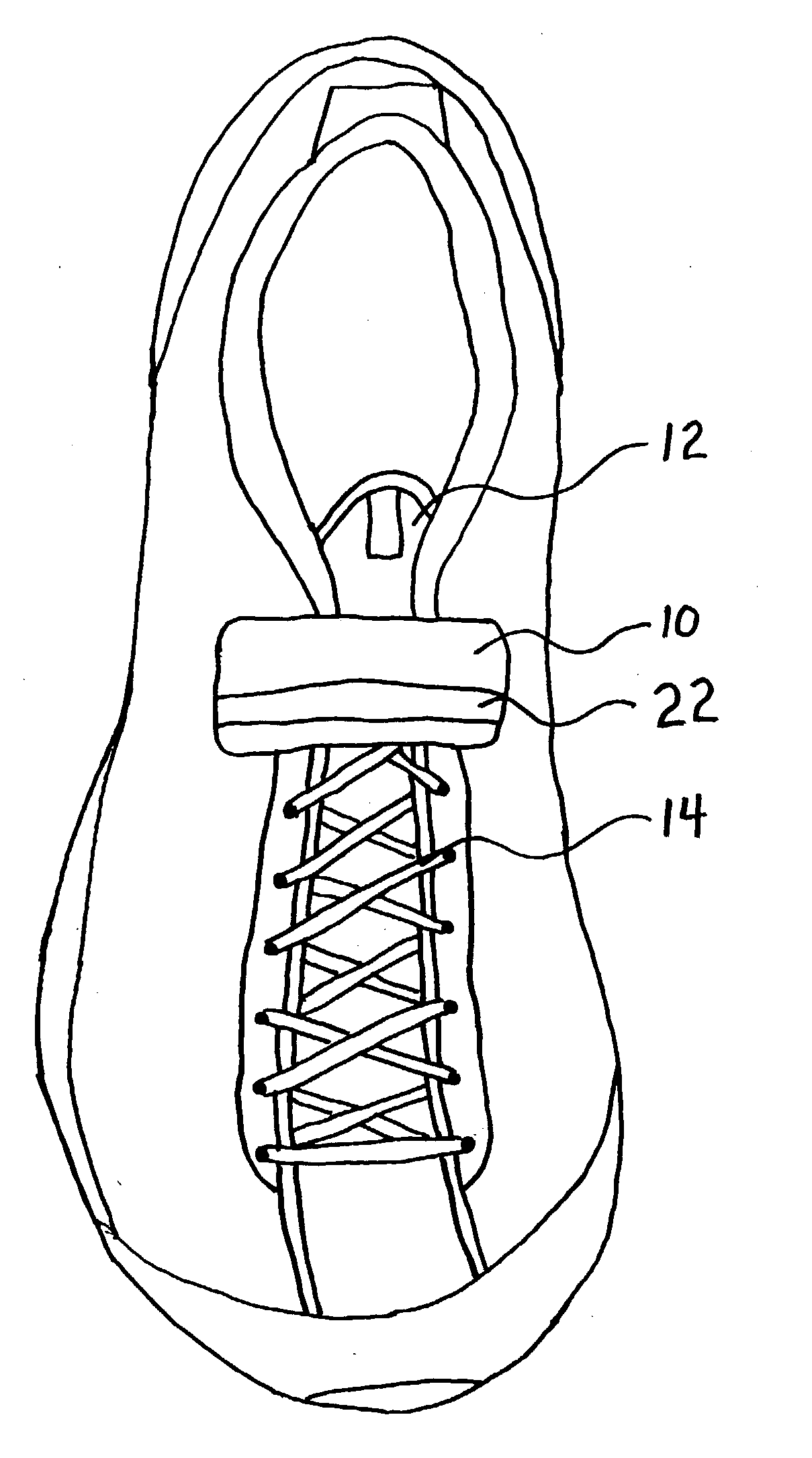
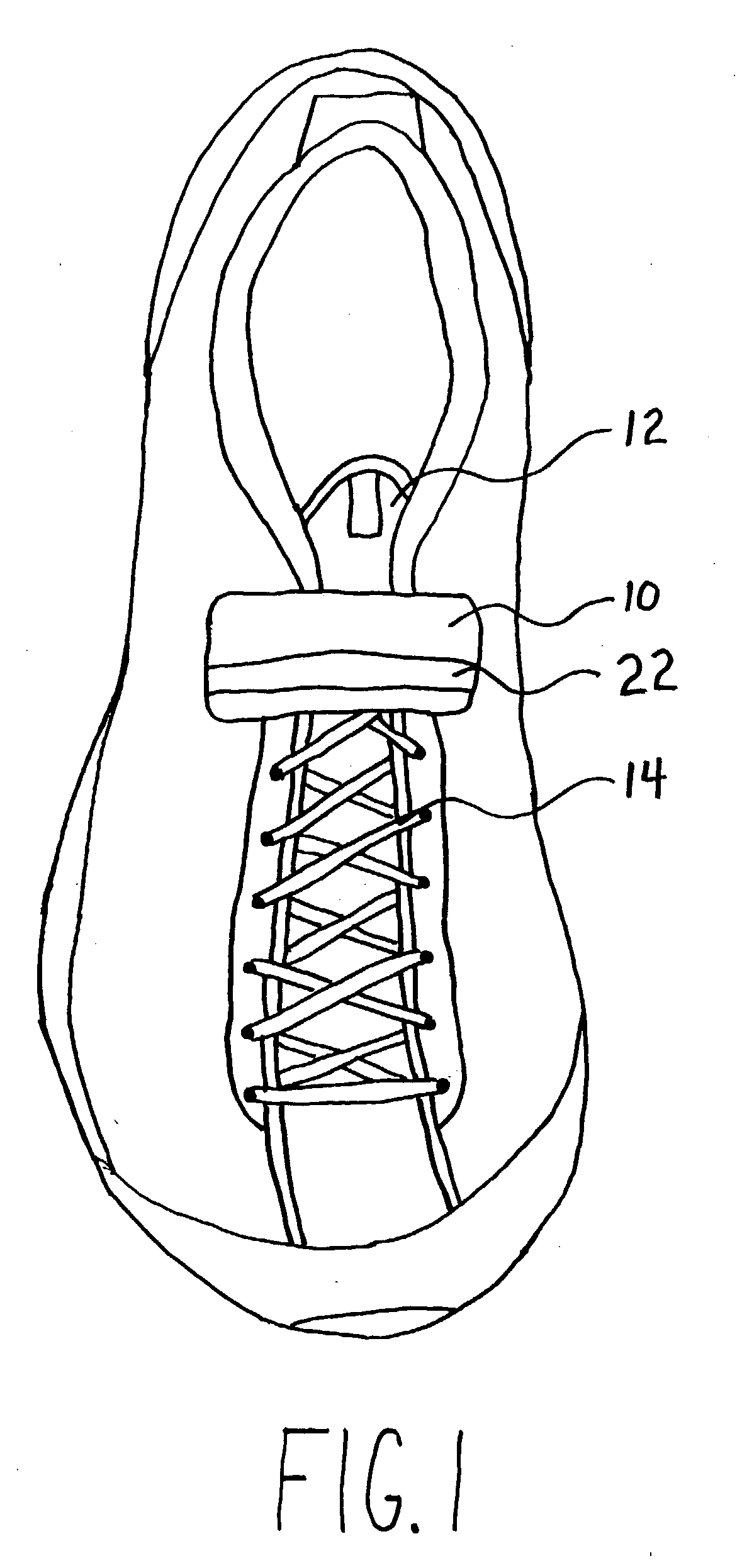
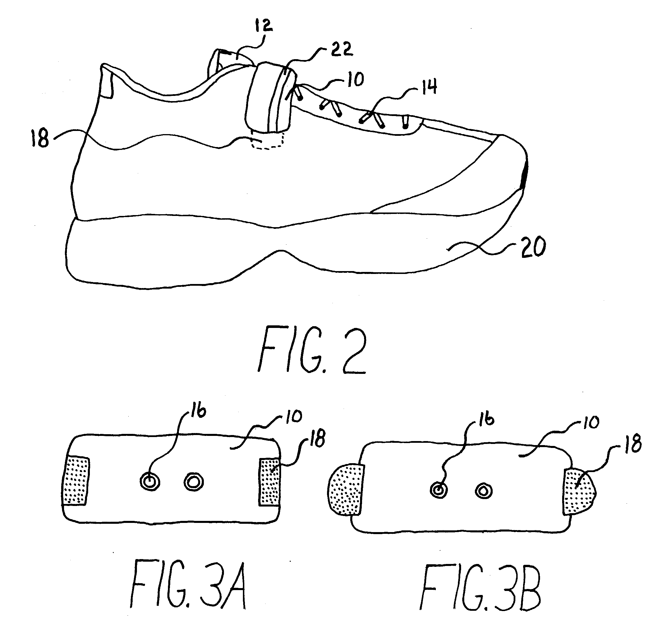
[0036] A preferred embodiment of the closure of the present invention is illustrated in FIG. 1 (top view) and FIG. 2 (side view). FIG. 1 shows the pouch 10 in place and closed on a shoe. The shoelaces 14 are secured inside the pouch 10 on top of the tongue 12. FIG. 1 shows the pouch 10 without the optional hook and loop element strips 18. FIG. 2 also shows the pouch 10 closed in place on a shoe. FIG. 2 shows the optional hook and loop element strips 18. The strips 18 are shown in hook and loop elements but any reusable closure system may be used. The strips 18 may also be in any shape. The strips 18 are used to secure the pouch 10 to the shoe during extreme foot activity.

[0037] At the top of the pouch 10 the closure 22 is secured (or closed). The strip 22 may be in a number of lengths or combinations (covered in FIGS. 5a and 5b). As with the optional bottom hook and loop element strips 18, an optional reusable closure system may be used. The smooth lightweight pouch 10 leaves the po...


PUM


Abstract

A shoe with improved lacing means includes a shoe, shoe laces (14) and a hook and loop element pouch (10). On the underside, the side making contact with the shoe, are two openings (16) that are used to slide the shoelaces through. With the pouch (10) open, the shoelaces (14) are pushed through the holes (16), pulled firmly and then tied as usual. Place the tied shoelaces (14) down into the pouch (10). There is a hook and loop element strip (22) on the opening making it easy to close, while keeping laces (14) secure. The pouch (10) can be attached to the shoe by hook and loop element strips (18) on both the right and left underside of the pouch (10). The pouch (10) will keep the shoelaces (14) from loosening, snagging and untying.

Description

[0001] Not applicable.[0002] 1. Field of Invention[0003] This invention relates to shoes, specifically to an improved securement, concealment and fastening device for shoes with laces.[0004] 2. Description for Prior Art[0005] Originally laces on shoes were designed to tie leaving laces to hang. This greatly increased the possibility for snagging on foreign objects and tripping. This problem has been partially solved by the implementation of lace securing devices, but these had and still have significant problems for the highly active foot activities (for example bicycling, baseball, football, basketball, and running).[0006] Thereafter, inventors created several types of shoelace devices to secure laces tight and / or conceal laces. U.S. Pat. No. 4,884,321 (1989), U.S. Pat. No. 4,879,787 (1989), U.S. Pat. No. 6,260,246 (2001) and U.S. Pat. No. 5,913,483 (1999) disclose similar ways to help aid in keeping laces fastened while tied. These patents use a device that when the laces are tied...

Claims


Application Information

Patent Timeline
IPC IPC(8): A43C7/02
CPCA43B1/0081A43B3/0031A43C7/02Y10T24/3742Y10T24/3703Y10T24/3716A43D999/00
Inventor JOHNSON, JAY ALLEN
Owner JOHNSON JAY ALLEN
Learn More