Air conditioned helmet apparatus

Active Publication Date: 2004-12-23
FEHER STEVE
View PDF19 Cites 95 Cited by
  • Summary
  • Abstract
  • Description
  • Claims
  • Application Information

AI Technical Summary

Benefits of technology

0006] Optionally, a forwardly facing air scoop is mounted to the outside upper surface of the helmet and directs ambient air to the heat pump for conditioning while also serving to protect the heat pump from possible impact or contact dam

Problems solved by technology

Considerable discomfort can result from wearing a helmet, especially the full-f

Method used


Image

  • Air conditioned helmet apparatus
  • Air conditioned helmet apparatus
  • Air conditioned helmet apparatus

Examples


Embodiment Construction

[0017] There are a number of different human activities that require or where it is highly desirable to wear, a helmet to protect the wearer against injury while engaging in the activity. For example, a helmet is desirably worn when riding a motorcycle or driving a race car since any accident could result in a blow being received to the head and if a helmet is worn the chances of reducing or avoiding injury altogether are substantially increased. On wearing a helmet while riding a motorcycle or during car racing, the driver is subjected to increased temperature about the head especially during warm weather or humid conditions which are rather uncomfortable for the driver / wearer. A motorcycle policeman, for example, must wear a helmet throughout long hours of a work shift and suffer the inconvenience associated therewith along with the normal high stress related to his employment.

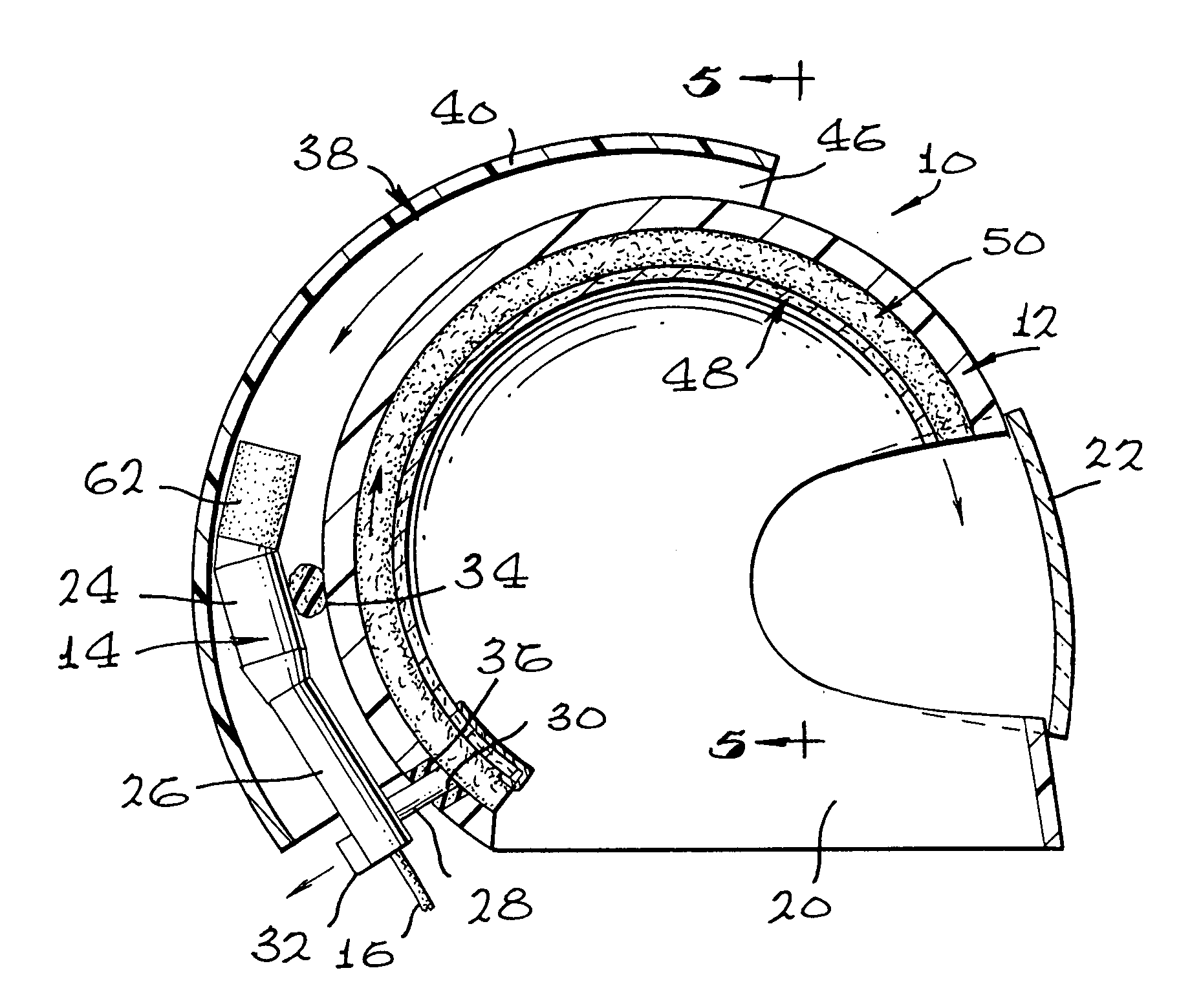
[0018] With reference now to the drawing and particularly to FIG. 1, a first embodiment of air conditione...


PUM


Abstract

A helmet (12) includes a thermoelectric heat pump (14) mounted onto a rear surface of the helmet shell (12) for delivering temperature conditioned air to the interior of the helmet shell. A multi-layer structure (48) on the helmet shell interior distributes conditioned air across the scalp and directly onto the face. An optional scoop (38) directs ambient air to the heat pump (14). Another version locates the heat pump (68, 84) remotely and conditioned air is transmitted to the helmet apparatus (70, 78) via a flexible conduit (72, 85).

Description

[0001] 1. Field of the Invention[0002] The present invention relates to a helmet apparatus especially adaptable for providing conditioned air about the head and face of the wearer, and which is light-weight and only requires relatively low-power electrical energization.[0003] 2. Description of Related Art[0004] There are many situations, both work oriented and sport, in which the wearing of a helmet is necessary or highly desirable. Exemplary of but a few instances where wearing a helmet for a relatively long period of time is required are: a motorcycle police officer; race car driver; and a military tank driver. Considerable discomfort can result from wearing a helmet, especially the full-face type, for even a short period of time particularly in warm or humid weather.SUMMARY OF INVENTION[0005] In the practice of a first embodiment of the invention there is provided a helmet consisting of the hard shell variety onto the rear of which is mounted an electrically energized heat pump t...

Claims


Application Information

Patent Timeline
IPC IPC(8): A42B3/28A61F7/00A61F7/02
CPCA42B3/285A61F2007/0002A61F2007/0076
Inventor FEHER, STEVE
Owner FEHER STEVE
Why Eureka
Try Eureka