
Screening apparatus

a technology of screen and screen body, which is applied in the direction of moving filter element filter, water/sludge/sewage treatment, artificial water canal, etc., can solve the problems of ineffective cleaning, limited screen effectiveness, blinding of screen in this situation,

Active Publication Date: 2004-12-30
SULZER MANAGEMENT AG
View PDF30 Cites 18 Cited by
  • Summary
  • Abstract
  • Description
  • Claims
  • Application Information

AI Technical Summary

Problems solved by technology

A screen in this situation can become blinded, i.e. blocked, by the solid matter in the mixture.
Such screens are limited in their effectiveness to allow water to flow freely over the weir.
In addition, during extreme conditions, the brush may become submerged which leads to ineffective cleaning and the screen becoming rapidly blinded.
Consequently, the screen becomes completely ineffective until the extreme conditions have subsided.
This design is not believed to be suitable for use in a sewerage system.

Method used


Image

  • Screening apparatus
  • Screening apparatus
  • Screening apparatus

Examples


Embodiment Construction

[0026] FIG. 1

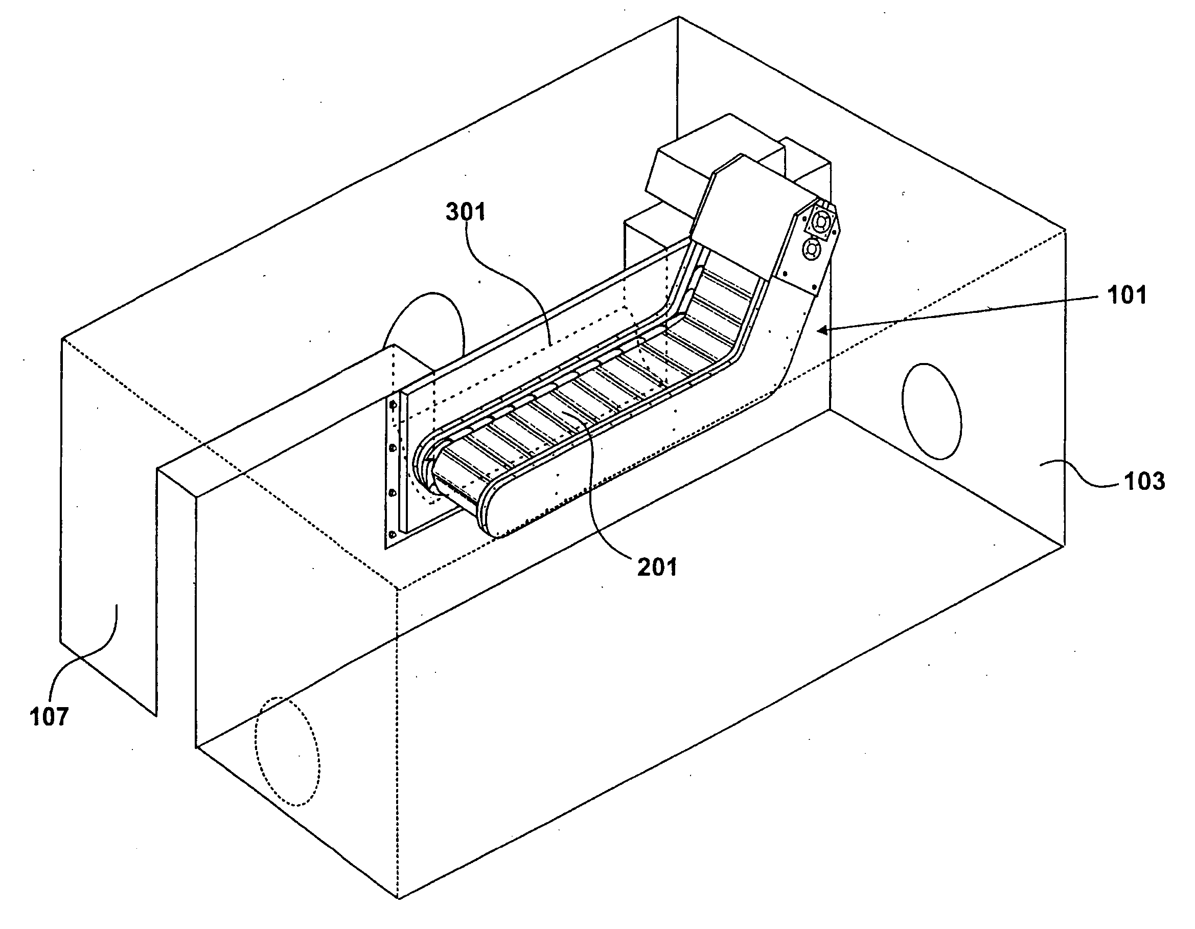
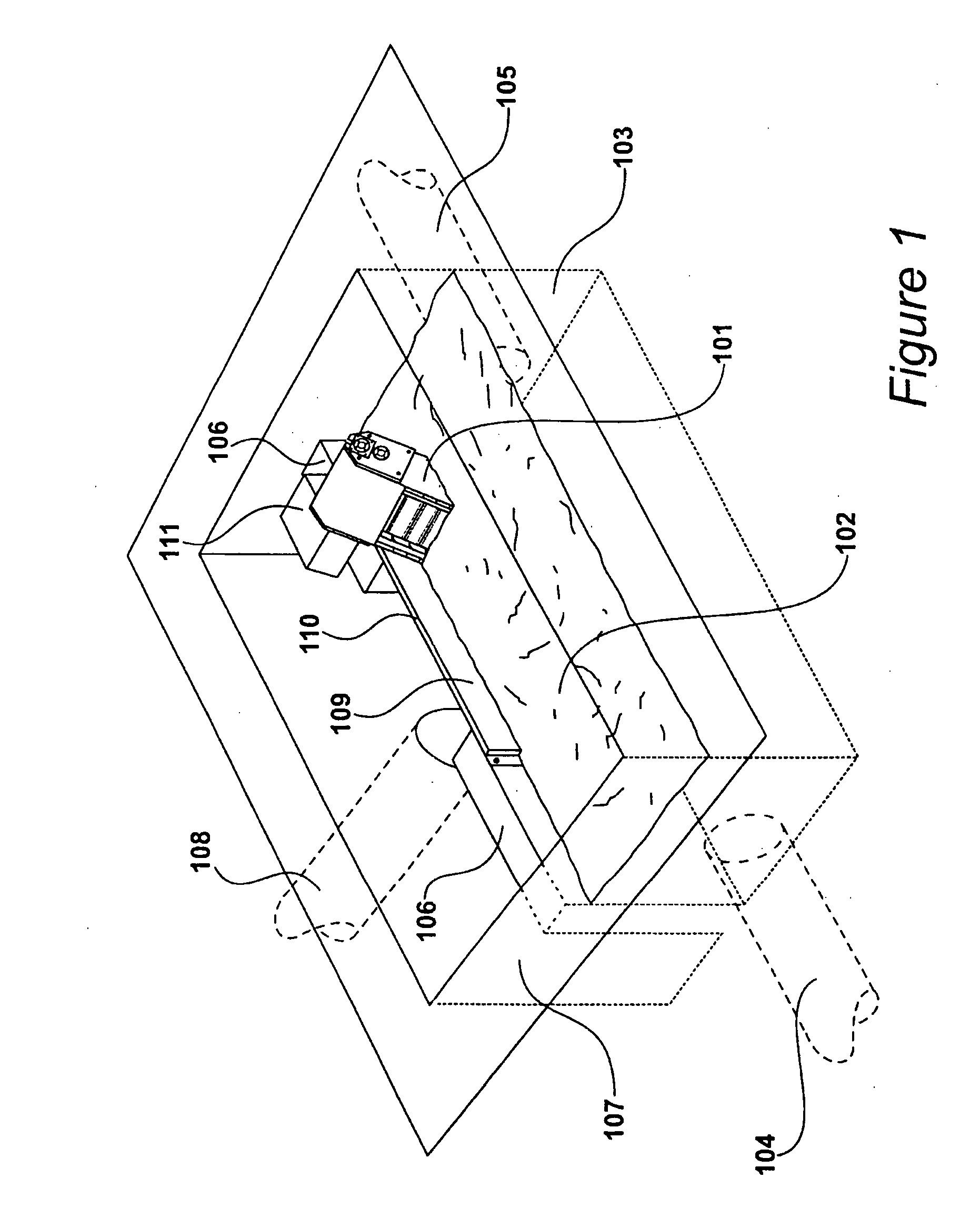
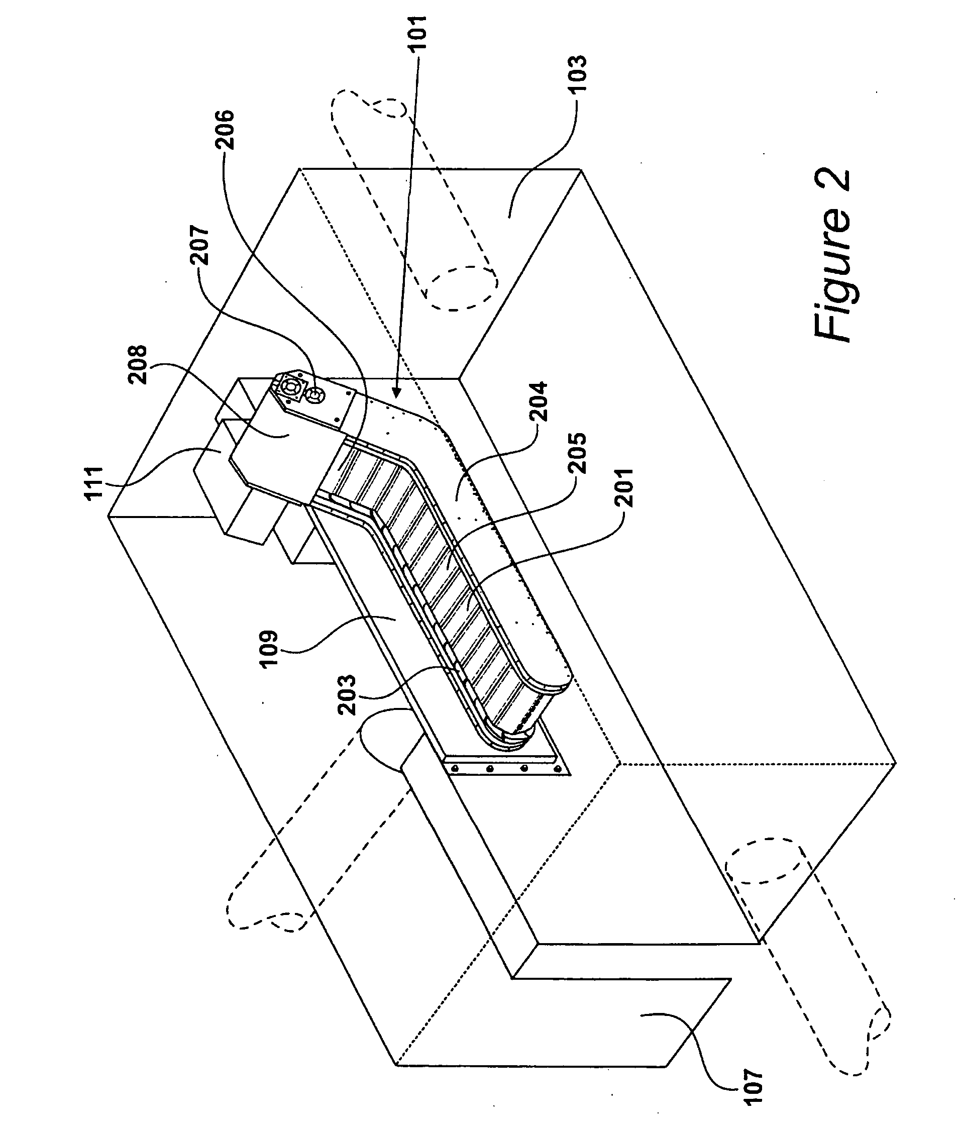
[0027] A screening apparatus 101 is shown partly submerged in sewage 102 in a continuation chamber 103 in FIG. 1. The level of sewage 102 illustrated in FIG. 1 is a typically high level that is reached when the sewerage system has received large amounts of rain water.

[0028] The sewage 102 is a liquid and solid mixture which flows into the chamber 103 from a sewer pipe 104. At least a portion of the sewage 102 exits the chamber 103 via sewer pipe 105 and may continue flowing to other parts of the sewerage system leading to a sewage treatment plant.

[0029] During periods when flow rates are low, all sewage entering via pipe 104 will subsequently exit via sewer pipe 105.

[0030] A concrete wall 106 of the chamber 103 separates said chamber from an overflow chamber 107. A section of the wall 106 is of a lower height than the sections either side of it, and the lower section defines a weir. During periods when flow rates along the sewer are high, the level in the chamber 103 be...


PUM

PropertyMeasurementUnit
Flow rateaaaaaaaaaa
Flexibilityaaaaaaaaaa
Widthaaaaaaaaaa

Abstract

Screening apparatus (101,901) for use at an overflow weir (301, 902) in a sewerage system. The apparatus comprises a continuous moving screen band (201,902) and a band cleaning mechanism (608). A first portion (801) of the screen band is configured to move along the weir towards one of its ends, and a second portion (803) of the screen band is configured to move along the weir towards its opposite end. A steeper portion (805) of the screen band extends to an elevated position (806) above the first and second portions, and the band cleaning mechanism is arranged to remove solid matter from the screen at said elevated position.

Description

[0001] 1. Field of the Invention[0002] The present invention relates to screening apparatus for use at an overflow weir in a sewerage system and a method of manufacturing screening apparatus. More specifically, the screening apparatus is configured for use with a side weir of a sewerage channel.[0003] 2. Description of the Related Art[0004] Sewerage channels carry a mixture of liquids and solids to treatment plants. During wet weather, some channels receive rain water and consequently their flow levels are raised. To manage increased flow rates, such channels are provided with overflow weirs which allow excess water to leave the sewerage system and enter a watercourse such as a river.[0005] In order to prevent undesirable solids from leaving the sewerage channel by the overflow weir and entering a watercourse, it is known to provide a screen along the weir. Such a screen allows a flow of water over the weir but screens out solid matter which is maintained in the flow in the sewerage...

Claims


Application Information

Patent Timeline
IPC IPC(8): B01D33/333E02B8/02E03F5/12
CPCB01D33/333E02B8/026E03F5/12E03F5/125
Inventor MIDDLETON, DAVID GRANT
Owner SULZER MANAGEMENT AG
Learn More