
Object matching via RFID

Active Publication Date: 2005-01-06
IBM CORP
View PDF11 Cites 34 Cited by
  • Summary
  • Abstract
  • Description
  • Claims
  • Application Information

AI Technical Summary

Benefits of technology

[0015] In addition, at least two RFID tags can be programmed with a customer identifier. Concurrently, one of the programmed RFID tags can be coupled to a consumer card held by a customer, while the remaining ones of the programmed RFID tags can be coupled to products which have been purchased by the customer. Similarly, at least two RFID tags can be programmed with a ticket number. Concurrently, one of the programmed RFID tags can be co

Problems solved by technology

While bar code based object tracking systems have proven to be highly effective in regard to efficiency and cost when compared to conventional pencil and paper tracking systems, bar code based inventory tracking systems remain deficient in their own regard.
For high volume applications, however, bar code scanning lacks a required level of efficiency and speed.
Despite many of the apparent advantages of RFID technology, deficiencies remain for some potential applications.
Specifically, while RFID technology can be effective for garden variety inventory tracking, or for high speed vehicle logging, RFID technology heretofore has not been applied to the problem of object matching.
More particularly, the problem of object matching entails the matching of two specific objects, for instance an object and a receipt, or two different objects such as disk reader and computer.

Method used


Image

  • Object matching via RFID
  • Object matching via RFID
  • Object matching via RFID

Examples


Embodiment Construction

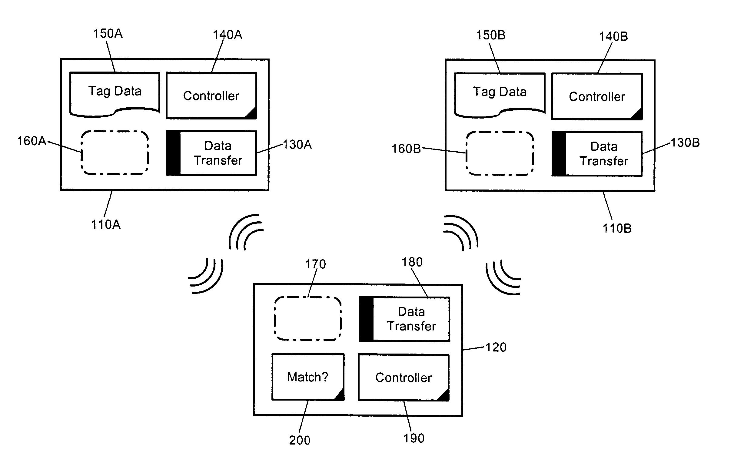
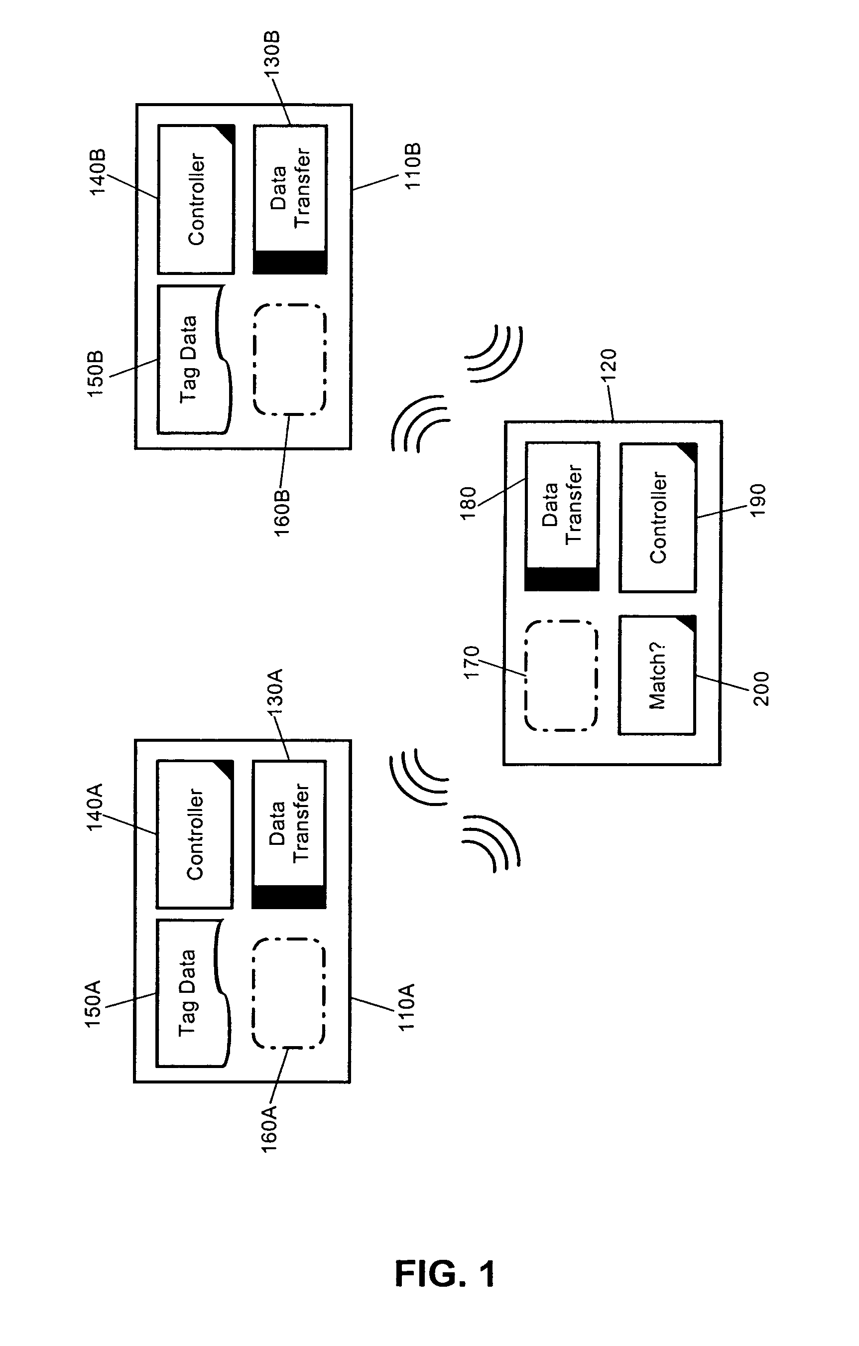
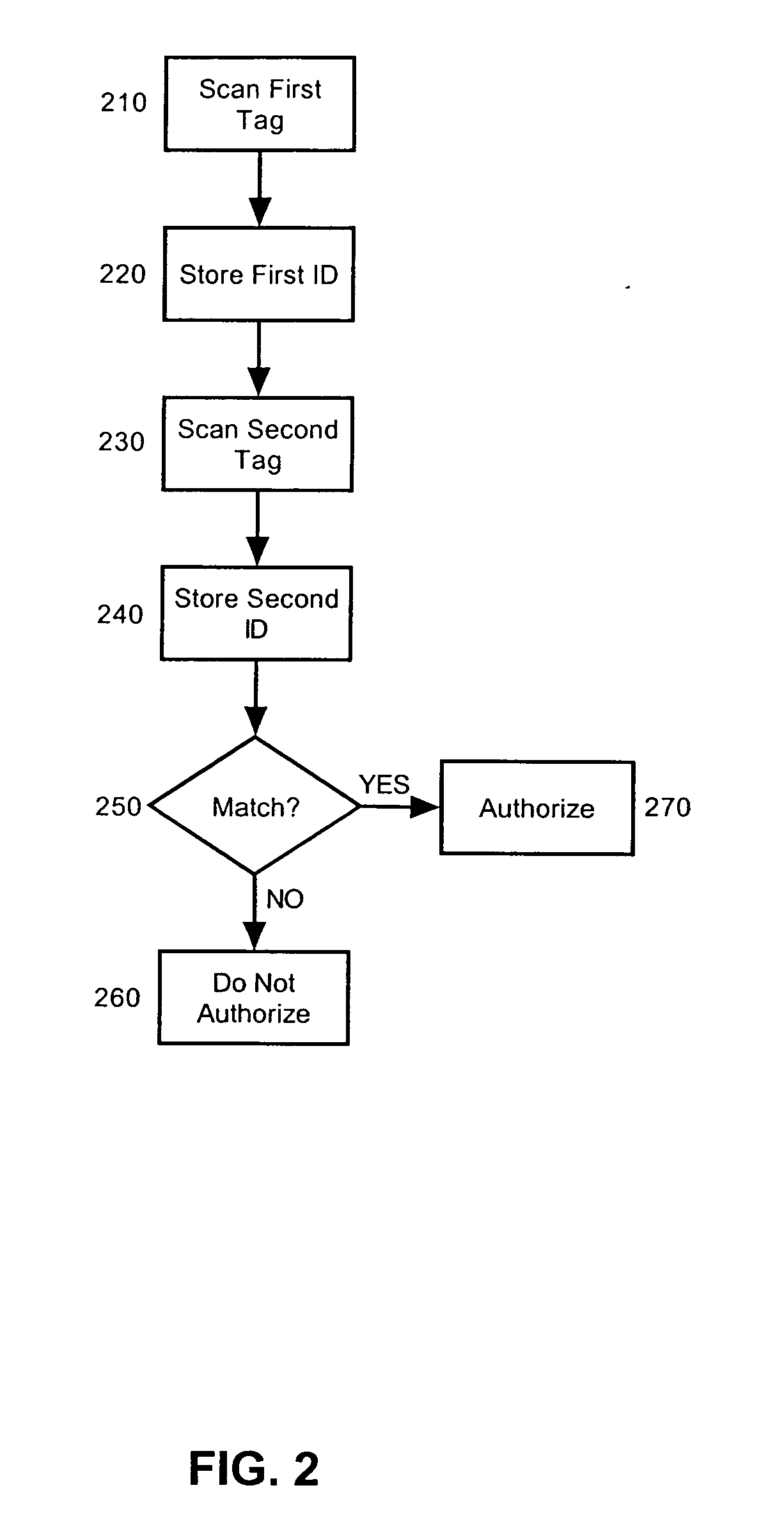
[0019] The present invention is an RFID object matching system and method. In accordance with the present invention, two or more paired objects each can be configured with an RFID tag. The respective RFID tags each can be programmed with data suitable to indicate that each of the associated objects to which the RFID tags have been affixed are related and thus “matched”. Subsequently, an RFID interrogator / reader can scan the RFID tags of at least two of the paired objects to determine that the objects have been appropriately matched. If the interrogator / reader concludes that the RFID tags do not contain data suitable to indicate that the two paired objects match, it can be concluded that the two objects are not paired. Otherwise, it can be definitively determined that the objects indeed are paired where the respective RFID tags of each produce the matching data.

[0020] Importantly, it is to be understood that the term paired objects refers to any set of tangible objects which are log...


PUM


Abstract

An object matching method, system and apparatus. The system can include a multiplicity of RFID tags storing corresponding tag data coupled individually to respective objects. Selected ones of the RFID tags can be programmed with tag data associating the selected ones of the RFID tags with one another. At least one RFID reader / interrogator can be configured to interrogate the RFID tags and responsive to the interrogation to read the corresponding tag data. Finally, matching logic can be programmed to determine whether interrogated ones of the RFID tags contain tag data indicating an association between coupled ones of the objects. Notably, the matching logic can be disposed in the RFID reader / interrogator.

Description

BACKGROUND OF THE INVENTION [0001] 1. Statement of the Technical Field [0002] The present invention relates to the radio frequency identification (RFID) and more particularly to RFID object tracking. [0003] 2. Description of the Related Art [0004] Conventional object tracking can range from ordinary inventory tracking to admissions ticket processing. For instance, in the context of inventory, object tracking can entail cataloging types, variations and quantities of physical items so as to know how much of any one physical item is present in inventory at any given time. Similarly, in the context of admissions ticket processing, object tracking can entail cataloging categories of admissions criteria and the like. Where object levels, such as inventory items or distributed tickets remain generally low and lack substantial variety and diversity from item to item, a conventional object tracking system can include a mere pencil and paper tracking method. In contrast, where object levels a...

Claims


Application Information

Patent Timeline
IPC IPC(8): G06K7/00G06K17/00G06K19/07
CPCG06K7/0008G06K17/0029G06K2017/0067G06K2017/0045G06K19/0723G06K17/00
Inventor AUPPERLE, BRYAN ERICMATHEWSON, JAMES M. II
Owner IBM CORP
Learn More