Electronic appliance having magnifying-glass display function, display controlling method, and display control program
a technology of display function and display control, applied in the direction of electric digital data processing, instruments, computing, etc., can solve the problem that images cannot be displayed in the enlarging/compressing operation
- Summary
- Abstract
- Description
- Claims
- Application Information
AI Technical Summary
Benefits of technology
Problems solved by technology
Method used
Image
Examples
first embodiment
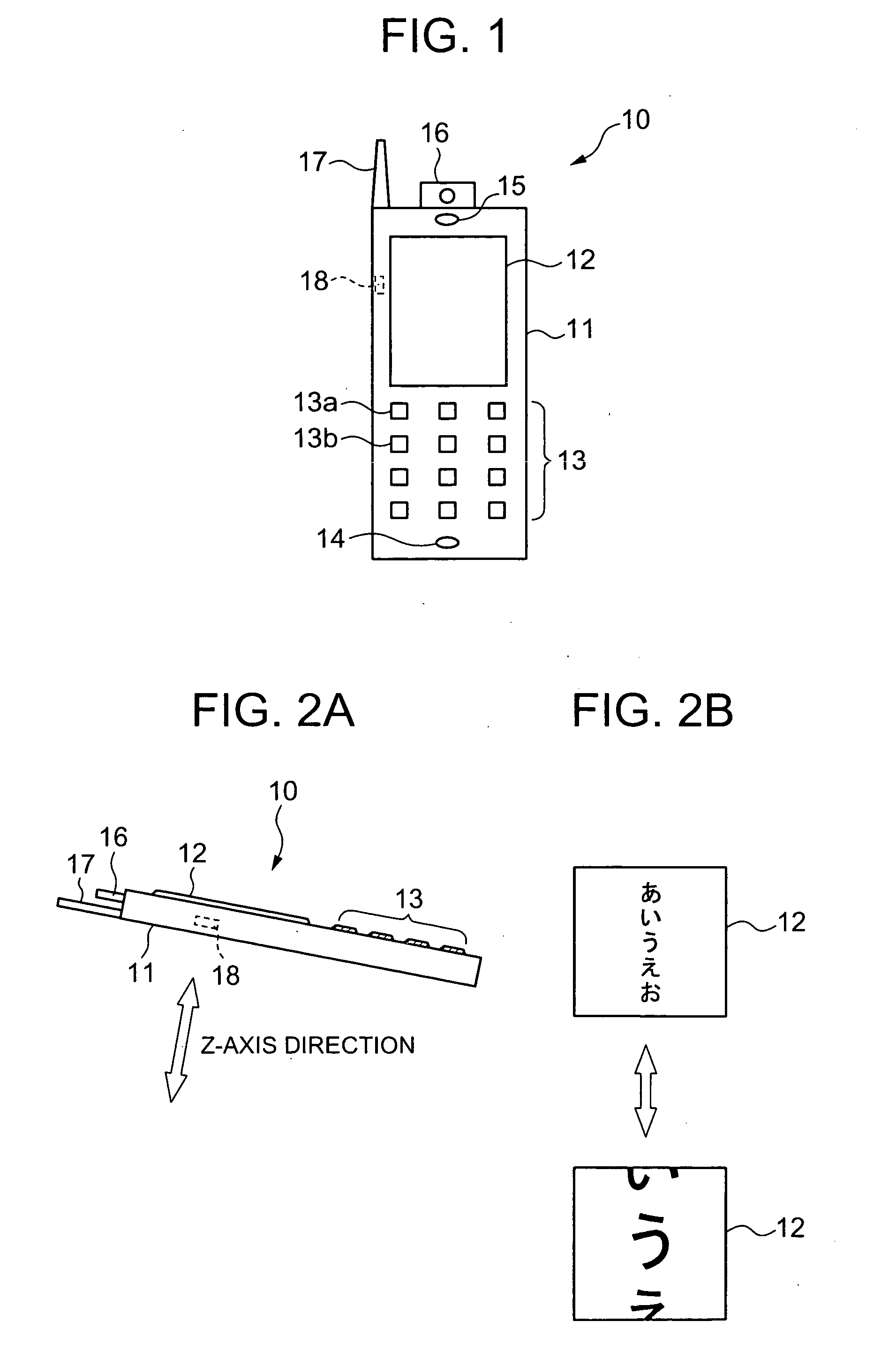
[0058] The input unit 13 is used so as to input data and also to instruct a function. This input unit 13 is arranged by containing dial / character buttons for entering a telephone number and a character; a power supply button for turning ON / OFF a power supply of this portable telephone 10; a transmission button used to make a telephone call and transmit an electronic mail; a function selecting button for selecting various functions provided on the portable telephone 10; a camera button for initiating the camera 16; and the like. Furthermore, in this first embodiment, the input unit 13 is provided with a special display mode button 13a for designating a special display mode; and an initializing display mode button 13b for designating an initializing display mode.
[0059] The above-explained special display mode corresponds to such a mode that a display size of information and a display range of this information displayed on the display screen are changed in response to a move direction ...
second embodiment
[0111] Next, a second embodiment mode of the present invention will be described.
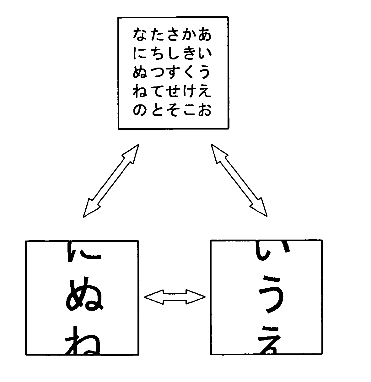
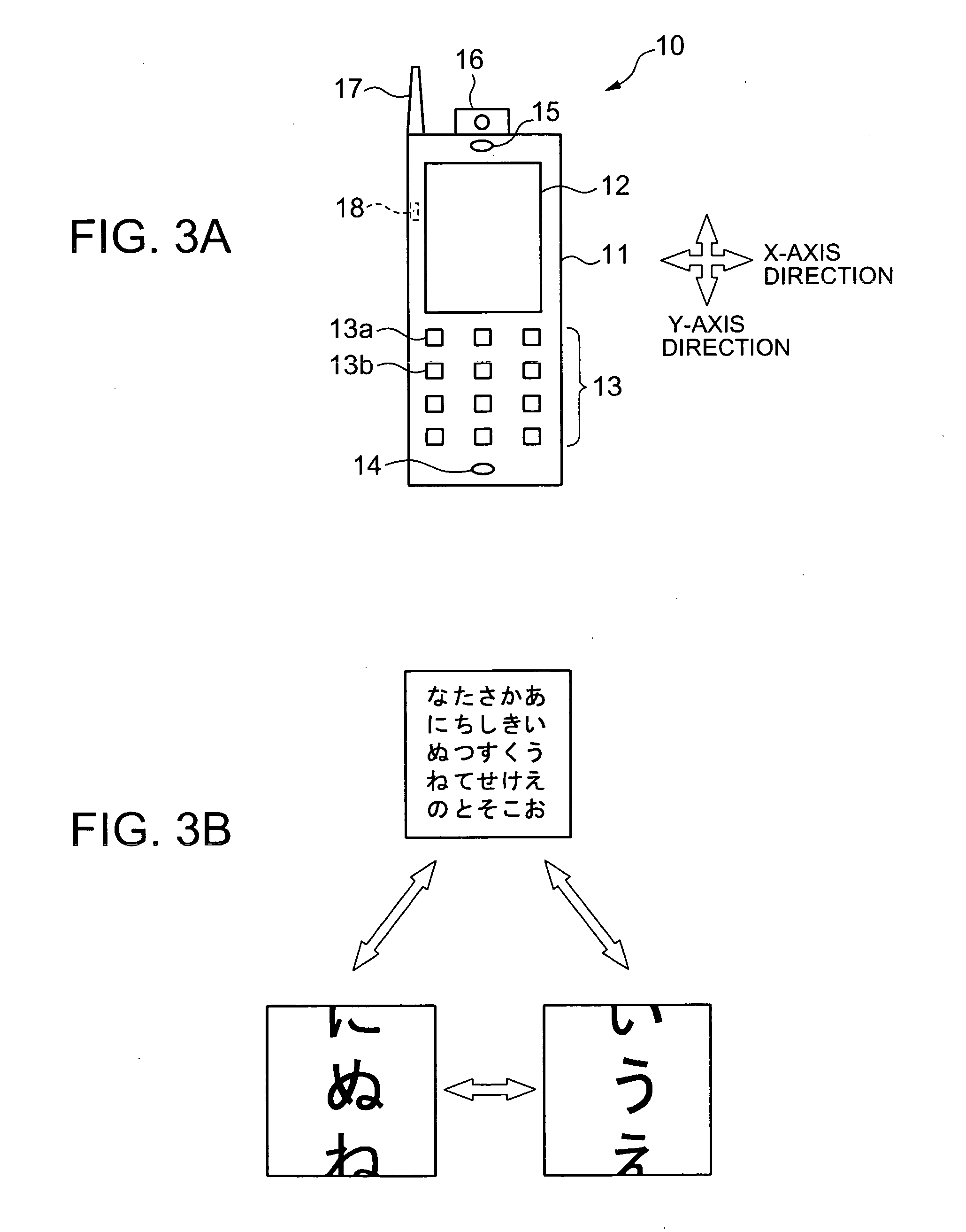
[0112] In the above-explained first embodiment mode, the display process operations as to the movement of the display unit 12 of the portable telephone 10 along the Z-axis direction has been described. In the second embodiment mode, a description will now be made of display process operations which also contain a display process operation with respect to movement of the display unit 12 along both an X-axis direction and a Y-axis direction. As previously explained in FIG. 3, with respect to the movement of the display unit 12 along the X-axis direction and the Y-axis direction, the display ranges are changed in connection with the movement. Similar to the first embodiment, the detections of the move amounts at this time are carried out by employing the sensor 18 which is constructed of the 3-axial acceleration sensor.
Second Processing Operation of Portable Telephone 10
[0113] Next, a description is made ...
third embodiment
[0130] A portable telephone, according to the present invention, is featured by that when a specific key input operation is made, image data is returned to an original display condition, namely an initial display condition, and then, the resultant image data is displayed. Concretely speaking, the above-described specific key implies the initializing display mode button 13b which has been allocated to one of the respective buttons of the input unit 13 shown in FIG. 1.
Third Processing Operation of Portable Telephone 10
[0131]FIG. 15 is a flow chart for describing display process operations of the portable telephone 10 according to the third embodiment of the present invention. This flow chart indicates display process operations of image data, which contain an initialization display process operation executed by depressing the initializing display mode button 13b. It should also be noted that the respective process operations shown in FIG. 15 are executed in such a manner that the cont...
PUM
 Abstract
Description
Claims
Application Information
 - R&D
- Intellectual Property
- Life Sciences
- Materials
- Tech Scout
- Unparalleled Data Quality
- Higher Quality Content
- 60% Fewer Hallucinations
Browse by: Latest US Patents, China's latest patents, Technical Efficacy Thesaurus, Application Domain, Technology Topic, Popular Technical Reports.
© 2025 PatSnap. All rights reserved.Legal|Privacy policy|Modern Slavery Act Transparency Statement|Sitemap|About US| Contact US: help@patsnap.com


