Loading floor for a vehicle and loading apparatus

a technology for loading apparatuses and vehicles, applied in the direction of refuse receptacles, transportation items, applications, etc., can solve the problems of reducing the usable loading space of vehicles, reducing the usable loading space, and reducing the usable loading area

Inactive Publication Date: 2005-01-06
FAURECIA INNENRAUM SYST
View PDF10 Cites 9 Cited by
  • Summary
  • Abstract
  • Description
  • Claims
  • Application Information

AI Technical Summary

Benefits of technology

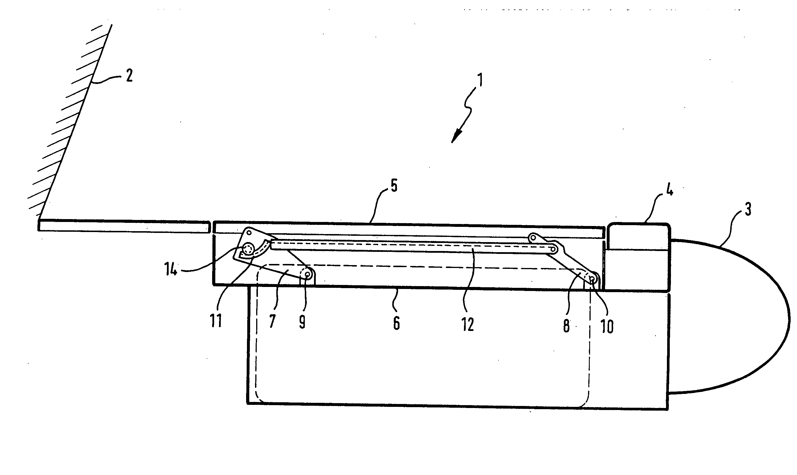
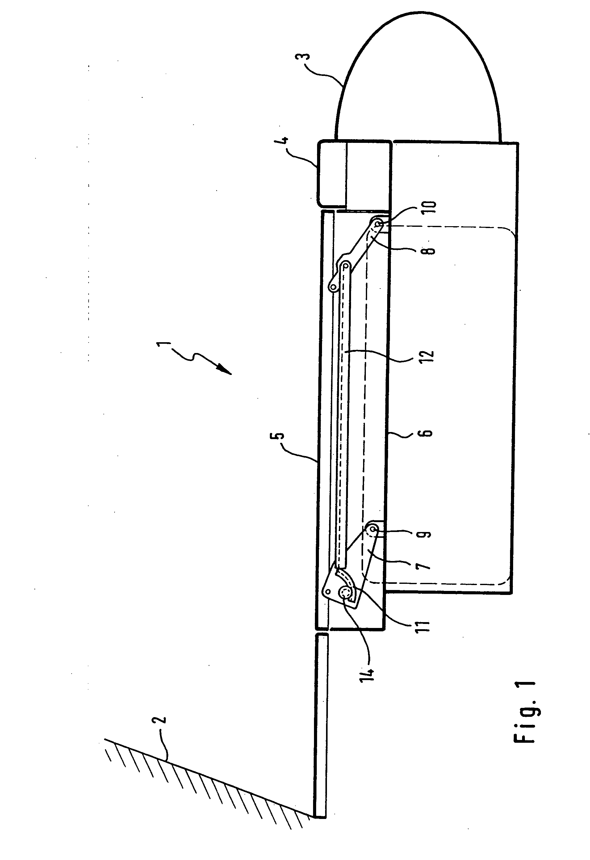
[0014] A special advantage of the invention is that the usable loading area is not, or is only minimally, reduced by the lift / pull-out loading floor and the corresponding loading apparatus. According to a preferred embodiment, this is accomplished such that parallelogram steering elements are provisioned for the height adjustment of the loading floor.
[0015] The parallelogram steering elements are linked to the vehicle floor at one end. The other end of each parallelogram steering element lies on the lower side of the loading floor. At least one of the parallelogram steering elements is configured so that it can be driven for adjusting the height of the loading floor.
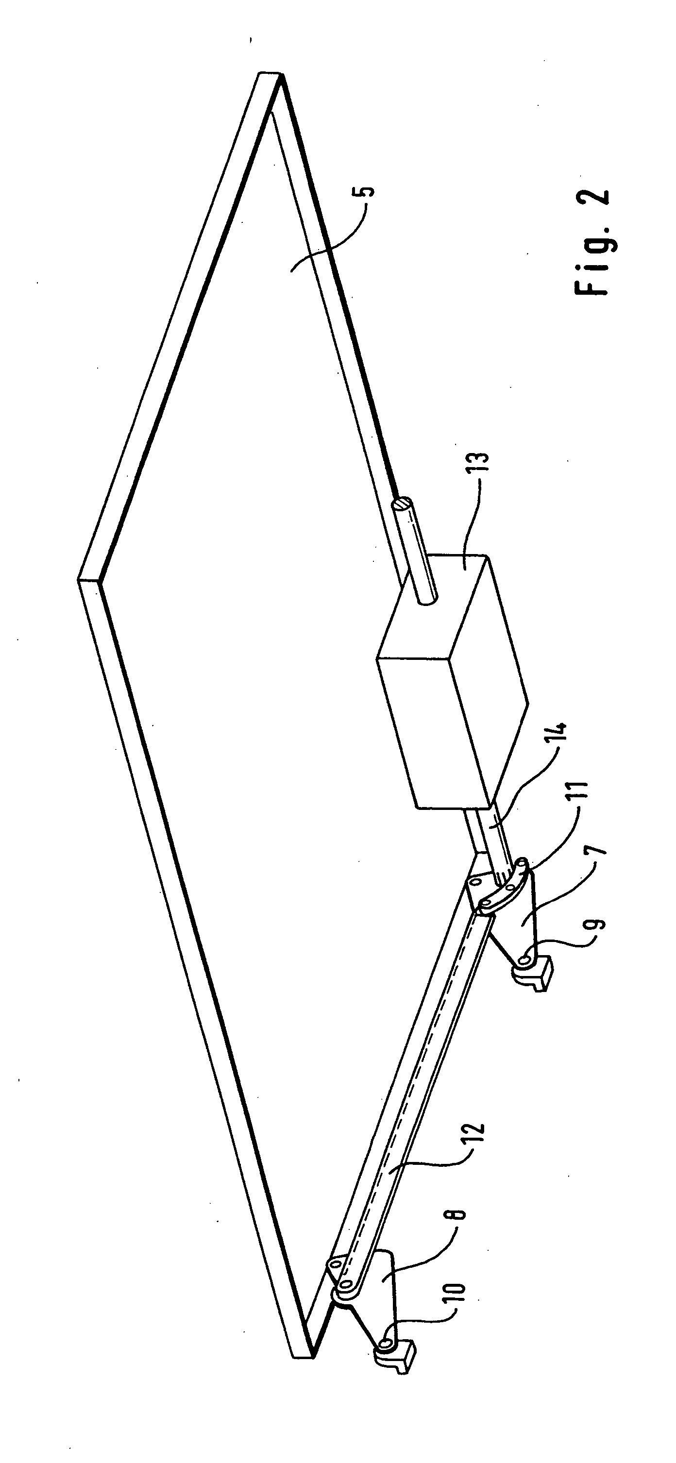
[0016] According to a preferable embodiment of the invention, at least one of the parallelogram steering elements exhibits a toothed segment, by means of which a driving force can be introduced, by means of a shaft, in order to raise or lower the loading floor. As pertains to this, the shaft is driven by a drive mechanism provisioned on the loading floor. The drive mechanism is preferably an electromechanical drive mechanism.
[0017] According to a further preferable embodiment of the invention, the toothed segment has a curved shape, in particular in the form of a circular segment. The curved or circular form can be configured concave or convex, with regard to the lower side of the loading floor.
[0018] According to a further preferable embodiment of the invention, the drive mechanism is provisioned on the lower side of the loading floor. Provisioning the drive mechanism on the lower side of the loading floor allows for a particularly space-saving configuration of the loading apparatus according to the invention, so that no or only little usable loading space is lost.
[0019] According to a further preferable embodiment of the invention, the drive mechanism is provisioned on the side of the loading floor that lies across from the loading edge of the vehicle in the retracted state of the loading floor. Thus, when the loading floor is extended, the drive mechanism fastened to the loading floor moves towards the loading edge.

Problems solved by technology

However, a common disadvantage of the previously known loading apparatuses is that, due to the pull-out mechanism for the loading floor, a considerable amount of loading area is lost.

Method used


Image

  • Loading floor for a vehicle and loading apparatus
  • Loading floor for a vehicle and loading apparatus
  • Loading floor for a vehicle and loading apparatus

Examples


Embodiment Construction

[0034] In a schematic side view, FIG. 1 shows loading area 1 of a vehicle, bordered by rear seat 2 towards the front of the vehicle. Loading edge 4 is located above fender 3 of the vehicle. Loading floor 5 is located behind loading edge 4.

[0035] Parallelogram steering elements 7 and 8 are provisioned on vehicle floor 6. Parallelogram steering elements 7 and 8 are connected with vehicle floor 6 such that they can move around axles 9, or 10 respectively. It is preferable that there is a pair of parallelogram steering elements 7 and 8 on each side of the vehicle, so that loading floor 5 lies on parallelogram steering elements 7 and 8.

[0036] Toothed segment 11 is located in parallelogram steering elements 7, which are the front parallelogram steering elements, with respect to the vehicle. Toothed segment 11 serves to introduce a driving force from a drive mechanism fastened to the lower side of loading floor 5 in order to lift loading floor 5, by means of a swinging motion of parallel...


PUM


Abstract

A loading apparatus for a vehicle, with loading floor provisioned in loading area of the vehicle, with a first set of elements for the vertical adjustment of loading floor within loading area, with a second set of elements for the horizontal movement of loading floor, specifically for extending and retracting loading floor out of and into loading area, and with drive elements for driving elements the first set of elements for the vertical adjustment of loading floor, wherein the second set of elements also serve to drive the first set of elements for the horizontal movement of loading floor.

Description

RELATED APPLICATION [0001] This application is a continuation of International Application PCT / EP03 / 05353 filed May 22, 2003, the contents of which are here incorporated by reference in their entirety.BACKGROUND OF THE INVENTION [0002] 1. Field of the Invention [0003] The invention relates to a loading floor for a vehicle and to a loading apparatus according to the characteristics and teachings of the disclosure herein. [0004] 2. Prior Art [0005] Various pull-out loading floors and loading apparatuses are known from the state of the art. A pull-out loading surface for station wagons is known from DE-OS 23 02 972, wherein guide rails are provisioned on the loading surface of the vehicle. The pull-out loading surface is mounted on these guide rails and can be moved on the guide rails on rollers. The items to be loaded can then be set onto the pulled out loading surface and pushed into the loading area of the vehicle. [0006] A loading apparatus for personal vehicles or transportation v...

Claims


Application Information

Patent Timeline
Patent Type & Authority Applications(United States)
IPC IPC(8): B60R5/04
CPCB60R5/04
Inventor NICK, ALBRECHTJURGEN, GEISSLINGERTHOMA, WULF
Owner FAURECIA INNENRAUM SYST
Why Eureka
Try Eureka