Storage virtualization computer system and external controller therefor

a virtualization computer and computer system technology, applied in the field of storage virtualization computer system, can solve the problems of multiple device connection, device-side psd access, and inability to perform

Active Publication Date: 2005-01-06
INFORTREND TECH INC
View PDF45 Cites 85 Cited by
  • Summary
  • Abstract
  • Description
  • Claims
  • Application Information

AI Technical Summary

Benefits of technology

The invention is a computer system that uses a specific type of interface called Serial ATA to connect storage devices. The system has a dedicated interconnect for each storage device, which allows for faster processing and better performance. The system also protects the control information along with the payload data, ensuring the information is secure.

Problems solved by technology

This patent discusses various examples of external storage virtualization controllers that use different types of interfaces to communicate with physical storages. These controllers offer improved performance and flexibility compared to previous methods but come with their limitations too. The technical problem being solved by the patent is how to efficiently manage and combine physical storages while ensuring optimal communication speed and reliability.

Method used


Image

  • Storage virtualization computer system and external controller therefor
  • Storage virtualization computer system and external controller therefor
  • Storage virtualization computer system and external controller therefor

Examples


Embodiment Construction

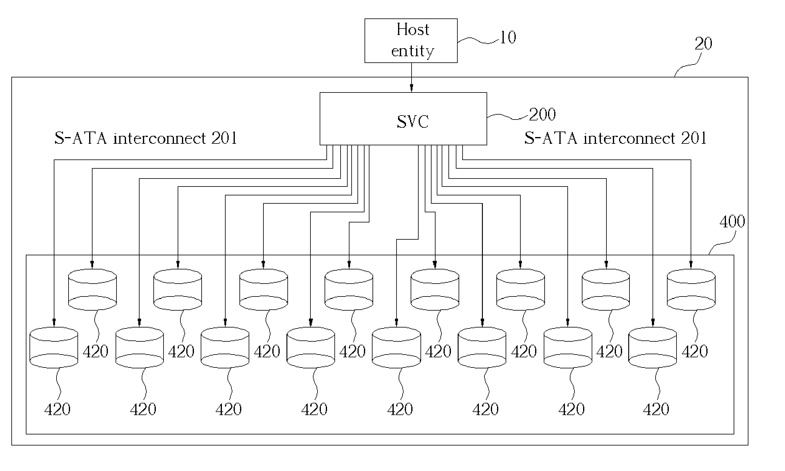
[0043] Please refer to FIG. 3, which is an embodiment block diagram of a storage virtualization computer system according to the present invention. In FIG. 3 Serial ATA is used as the primary device-side IO device interconnects. The computer system comprises a host entity IO and a connected storage virtualization subsystem (SVS) 20. Although there is illustrated in FIG. 3 only one host entity 10 connected with one SVS 20, there can be more than one SVS 20 attached to the host entity 10 or more than one host entity 10 can be attached to the SVS 20 or both.

[0044] The host entity 10 can be a host computer, such as a server system, a workstation, a PC system, or the like. The SVS 20 comprises a storage virtualization controller 200, which can be a RAID controller or a JBOD emulator, and a physical storage device array (PSD array) 400 connected by Serial ATA interconnect 201. Although only one PSD array 400 is illustrated here, more then one PSD array 400 can be attached to the SVC 200....


PUM


Abstract

A storage virtualization computer system. The storage virtualization computer system comprises a host entity for issuing an IO request, a storage virtualization controller coupled to the host entity for executing IO operations in response to the IO request, and a at least one physical storage device, each coupled to the storage virtualization controller through a point-to-point serial-signal interconnect, for providing storage to the storage virtualization computer system through the storage virtualization controller. As an example, the point-to-point serial-signal interconnect can be a Serial ATA IO device interconnect.

Description


Claims


Application Information

Patent Timeline
Owner INFORTREND TECH INC
Why Eureka
Try Eureka