Electronic volume measuring equipment

a technology of volume measurement and equipment, applied in the direction of volume measurement apparatus/methods, instruments, measurement devices, etc., can solve the problems of catastrophic collapse, substantial corrosion related defects and failures of reinforcing steel, and corrosion

Inactive Publication Date: 2005-01-13
DICKES GUY
View PDF2 Cites 20 Cited by
  • Summary
  • Abstract
  • Description
  • Claims
  • Application Information

AI Technical Summary

Benefits of technology

Electronic Volume Measuring Equipment utilizes electronic gas mass flow technology in a manner to provide accurate volume measurement of air tight containers, voids in concrete, other air tight structures and piping systems and tanks. There are three variations of the process.

Problems solved by technology

Routine inspection of bridges, particularly in Florida, uncovered substantial corrosion related defects and failures of the reinforcing steel.
Failure of this steel can result in catastrophic collapse.
Further in-depth investigation by numerous state Departments of Transportation and independent engineering firms have uncovered widespread problems throughout the post-tensioned bridge construction industry
It is in these areas that corrosion can occur.
Major structural damage caused by corrosion has been uncovered.
Often, the only access to the voids is through a small (½ inch diameter-typical) hole, making visual inspection and conventional repair nearly impossible.

Method used


Image

  • Electronic volume measuring equipment
  • Electronic volume measuring equipment
  • Electronic volume measuring equipment

Examples


Embodiment Construction

of the INVENTION

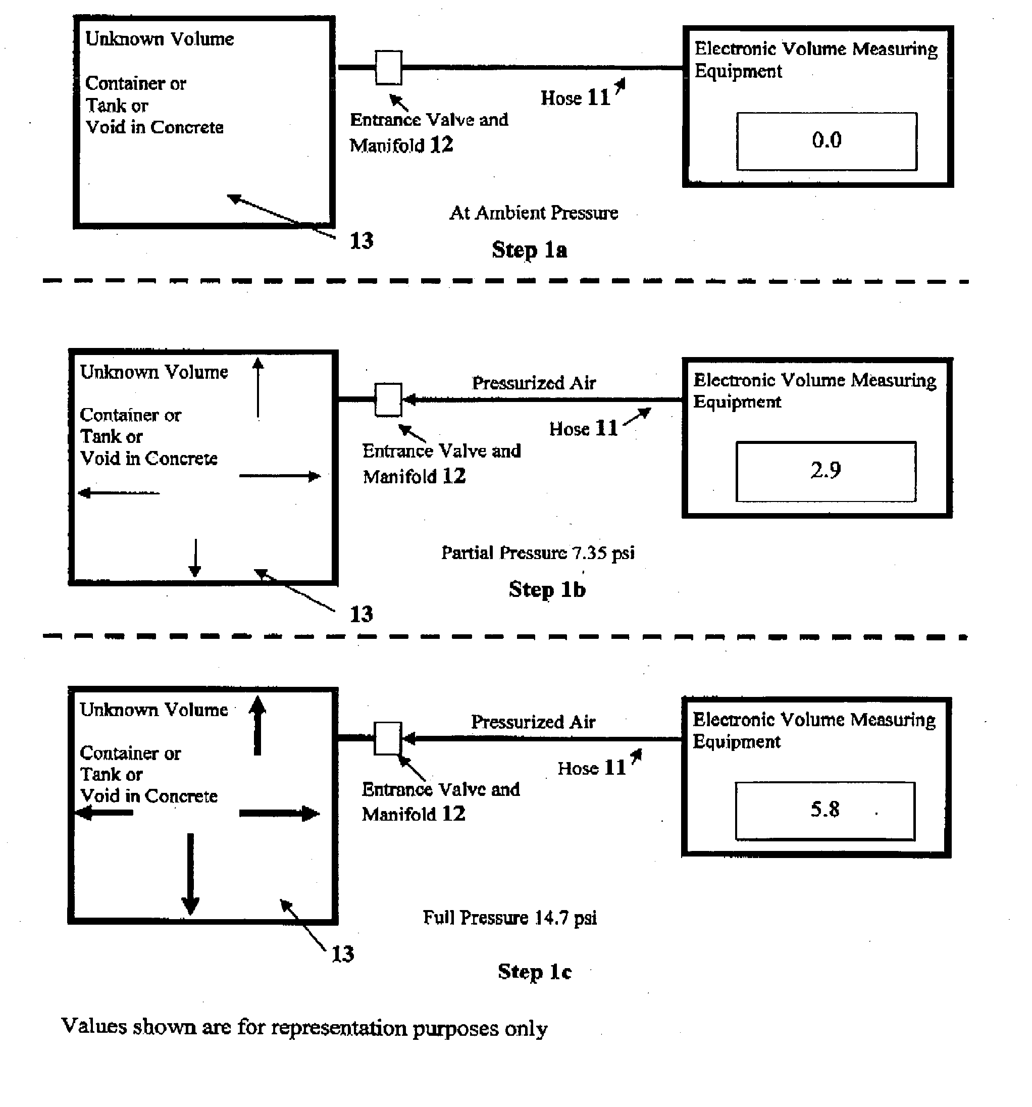
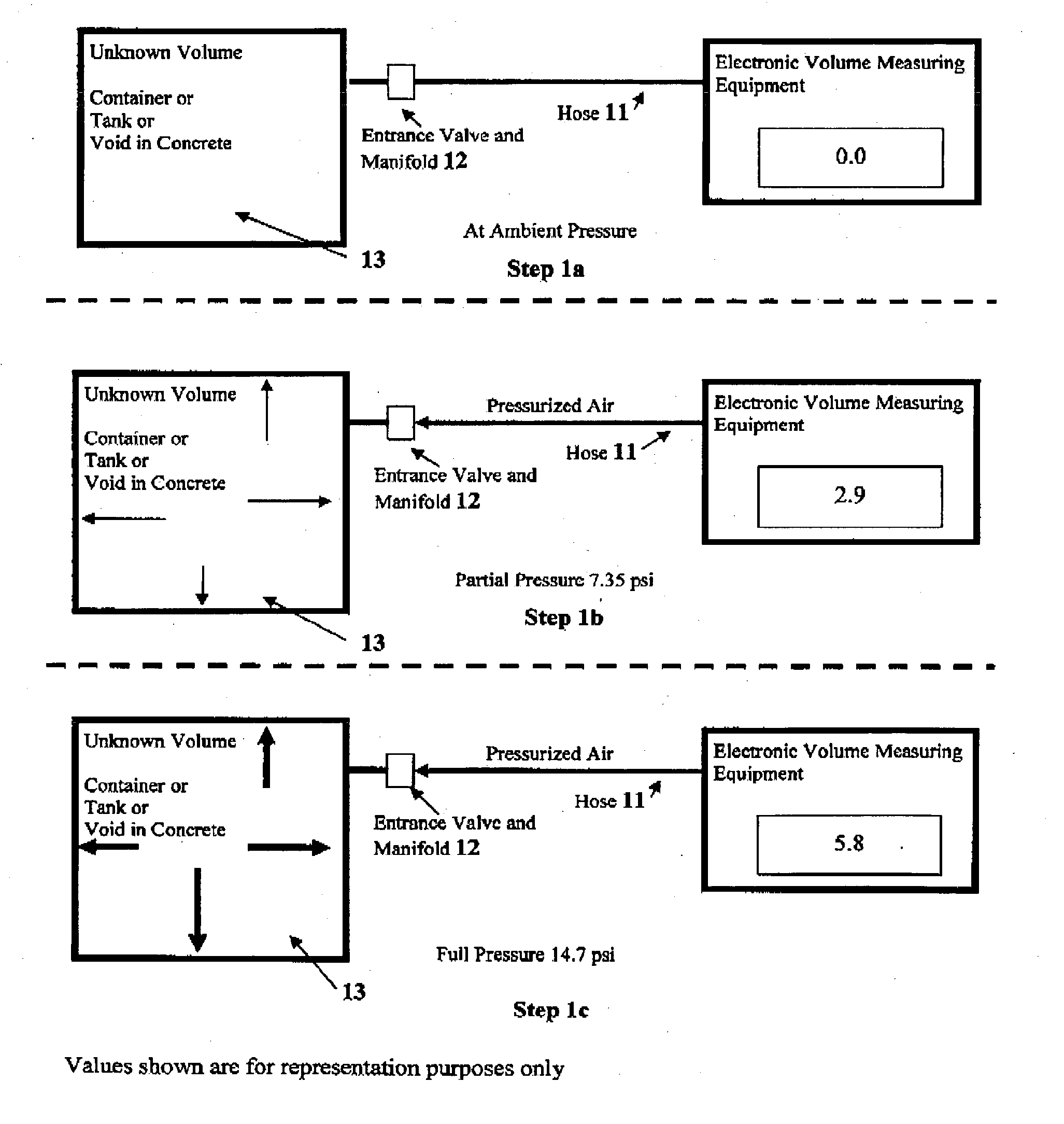
The Electronic Volume Measuring Equipment utilizes commercially available electronics and mechanical components in a manner different than the purpose for which that equipment was originally designed.

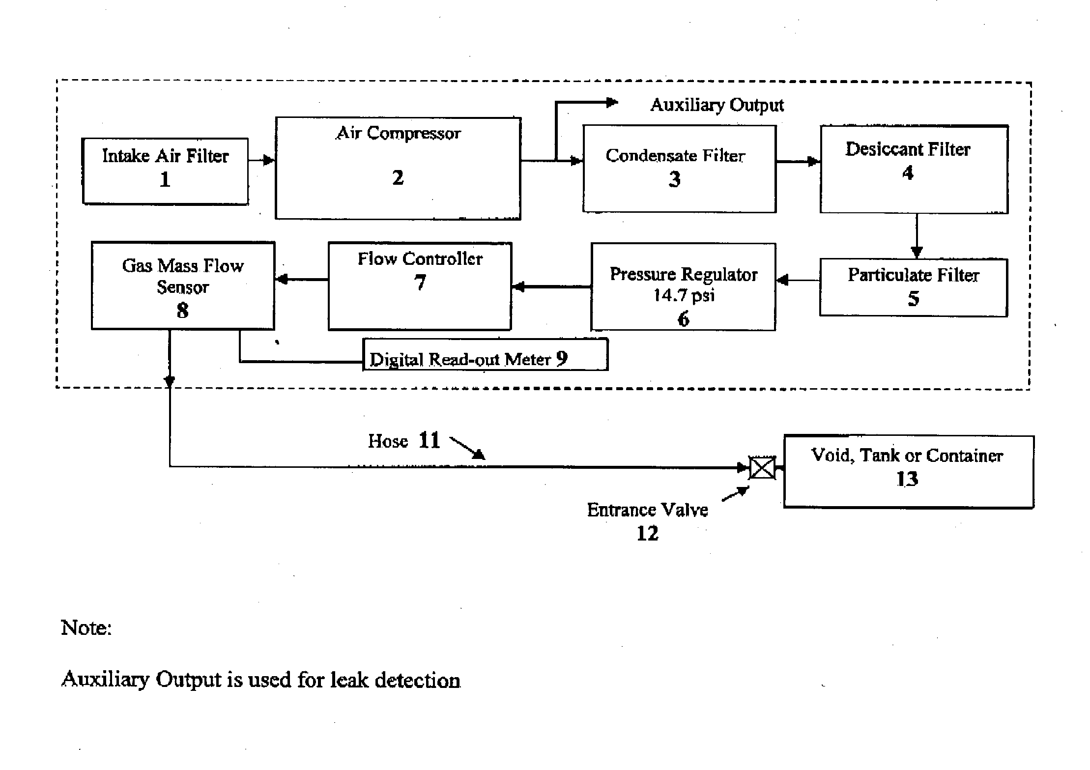
There are three primary components and numerous secondary support components of this equipment. The primary components are the gas mass flow sensor 8, the digital read-out meter 9 and the pressure regulator 6. The remaining components provide protection of the equipment and controlled flow through the apparatus.

The primary equipment includes an electronic gas mass flow sensor 8 that measures the mass of a gas passing through it. It is designed to measure gas flow rate rather than volume. This mass flow meter is connected electronically to a ‘totalizer’ digital read-out meter 9, to provide total gas mass, rather than gas flow rate. The pressure regulator provides accurate control of the air mass pressure. This equipment is typically used in an industrial or laborator...


PUM


Abstract

Electronic Volume Measuring Equipment is designed to measure any air tight space, void, container, piping system, or tank utilizing pressurized air, gas or vacuum. It uses electronic gas mass flow technology to achieve accurate results. Added benefits allow for the location of leaks prior to volume measurement.

Description

CROSS REFERENCE to RELATED APPLICATIONS Not applicable STATEMENT REGARDING FEDERALLY SPONSORED RESEARCH or DEVELOPMENT Not applicable REFERENCE TO SEQUENCE LISTING, TABLE, OR COMPUTER LISTING COMPACT DISK Not applicable BACKGROUND OF THE INVENTION Electronic Volume Measuring Equipment originated in response to the needs of the Post-Tensioning Industry within the construction industry. In the late 1990's it was determined that previously approved construction techniques, materials, engineering and inspection used in the cement grouting of hollow ducts used in the post-tension industry were substandard. These ducts are used to carry post-tensioned steel reinforcing strand from one end of a concrete structure to the other providing active reinforcement to the concrete. Such structures include bridges, buildings and tanks. After the installation of the post-tensioning strand is completed, the ducts are filled with a fluid cementitious grout to provide structural capacity and more im...

Claims


Application Information

Patent Timeline
Patent Type & Authority Applications(United States)
IPC IPC(8): G01F1/00G01F17/00
CPCG01F17/00
Inventor DICKES, GUY
Owner DICKES GUY
Why Eureka
Try Eureka