Method and apparatus for determining toner level in electrophotographic print engines

a technology of electrophotography and toner level, applied in the field of methods and apparatus, can solve the problems of inability to translate directly between, and the determination of a low toner level in a cartridge is extremely inaccura

Inactive Publication Date: 2005-01-13
FIERY LLC +1
View PDF42 Cites 19 Cited by
  • Summary
  • Abstract
  • Description
  • Claims
  • Application Information

AI Technical Summary

Benefits of technology

In another aspect of the present invention, each page of the multi-page document is rasterized and evaluated prior to printing. The toner usage for the entire doc

Problems solved by technology

However, in a multipass color process, multiple images must be superimposed on one another on the sheet of paper in a direct transfer system, thus requiring multiple passes of the paper or image carrier through the print engine.
When dealing with multiple print

Method used


Image

  • Method and apparatus for determining toner level in electrophotographic print engines
  • Method and apparatus for determining toner level in electrophotographic print engines
  • Method and apparatus for determining toner level in electrophotographic print engines

Examples


Embodiment Construction

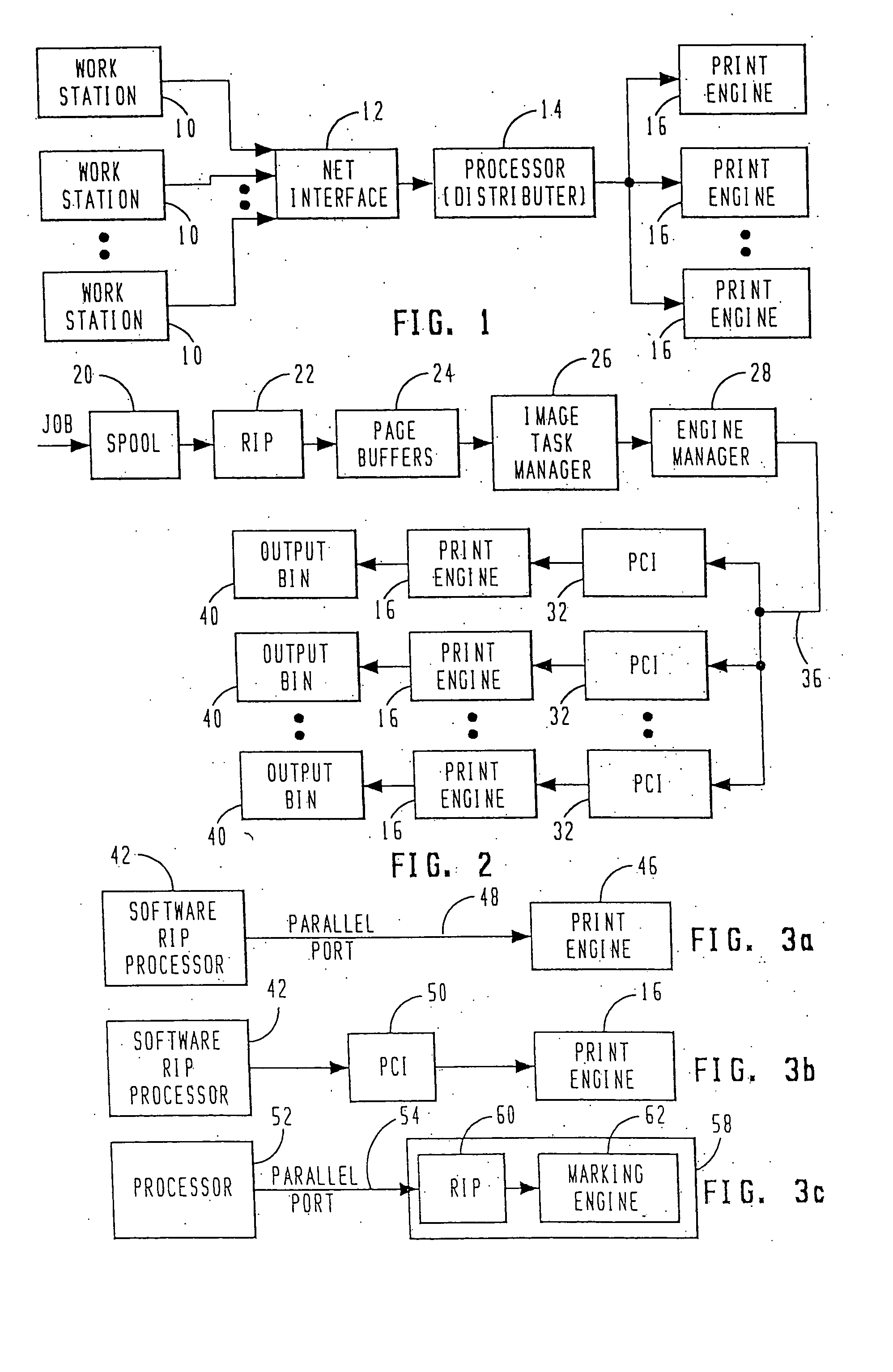
Referring now to FIG. 1, there is illustrated a block diagram of the overall operation of the virtual printing system. A plurality of workstations 10 are provided, which workstations 10 comprise general personal computers or other terminals that allow a user to create print jobs. Each of the workstations is networked through a network interface 12, which is a conventional type of general network interface such as an Ethernet® network interface. This allows each workstation 10 to send its print job to a central processor 14, which processor is operable to process the print jobs in accordance with the system of the present invention and distribute these print jobs to multiple print engines 16. As will be described hereinbelow, the processor 14 is operable to disassemble the print job, parse the print job into different pages and distribute the parsed pages in a predetermined manner in accordance with the present invention. It should be understood that a print job, although initiated ...


PUM


Abstract

The toner in the toner cartridge is determined by taking each of the rasterized images output by the RIP and evaluating the pixel levels over the surface thereof. The average value is determined as a percentage of the maximum toner that can be applied to the page. This is then subtracted from a toner value and a remaining toner level determined. Further, all pages of the rasterized document can be evaluated to predetermine the toner level after printing. If this falls below a predetermined minimum, printing is inhibited for that document.

Description

TECHNICAL FIELD OF THE INVENTION The present invention pertains in general to electrophotographic printers and, more particularly, to a plurality of print engines arranged in parallel to process print jobs in a parallel manner. BACKGROUND OF THE INVENTION Electrophotographic print engines have been utilized with both printers and copiers. In a printer, the print engine is typically interfaced with a computer to select and organize fonts or bit map the images. In a copier application, the print engine is interfaced with an input device that scans the image onto the photoconductor drum of the print engine. However, a CCD device could also be utilized in this application in the form of a CCD scanner. In either of the applications, a conventional print engine for a monochrome process would typically feed a single sheet of paper and pass it by the photoconductor drum for an image transfer process and then pass it to a fuser. Thereafter, the completed sheet will be output. Multiple copy...

Claims


Application Information

Patent Timeline
IPC IPC(8): G03G13/08G06F3/12G06F15/00
CPCG03G13/08G03G2215/0888G06K15/02G06K15/12G06K15/1823G03G15/556G06F3/1235G06F3/1285G03G15/5087G03G15/553G03G15/0856G06F3/121
Inventor BARRY, MICHAEL W.BARTHOLMAE, JACK N.ROWE, FRANCIS A.TOMPKINS, E. NEALZUBER, PETER A.
Owner FIERY LLC
Why Eureka
Try Eureka