Apparatus for controlling image processing and a method for controlling image processing

a technology of image processing and apparatus, applied in the direction of electrographic process, digital output to print units, instruments, etc., can solve the problems of unfavorable performance, inability to form a page contained in different jobs on the right and reverse sides of one sheet, etc., and achieve the effect of controlling image processing

Inactive Publication Date: 2005-01-13
CANON KK
View PDF2 Cites 40 Cited by
  • Summary
  • Abstract
  • Description
  • Claims
  • Application Information

AI Technical Summary

Problems solved by technology

Since each printing job transferred from a host computer is processed for printing individually in the conventional image processing apparatus described above, there are encountered the problems given below.
Therefore, if a printer takes a long time to be actuated and suspended, a waiting time between jobs becomes longer, leading to an unfavorable performance.
2) For a printer connected to an image processing apparatus, which is capable of printing on the right and reverse sides of one printing sheet, it is impossible to form a page contained in different jobs on the right and reverse sides of one sheet.

Method used


Image

  • Apparatus for controlling image processing and a method for controlling image processing
  • Apparatus for controlling image processing and a method for controlling image processing
  • Apparatus for controlling image processing and a method for controlling image processing

Examples


first embodiment

[0041] (First Embodiment)

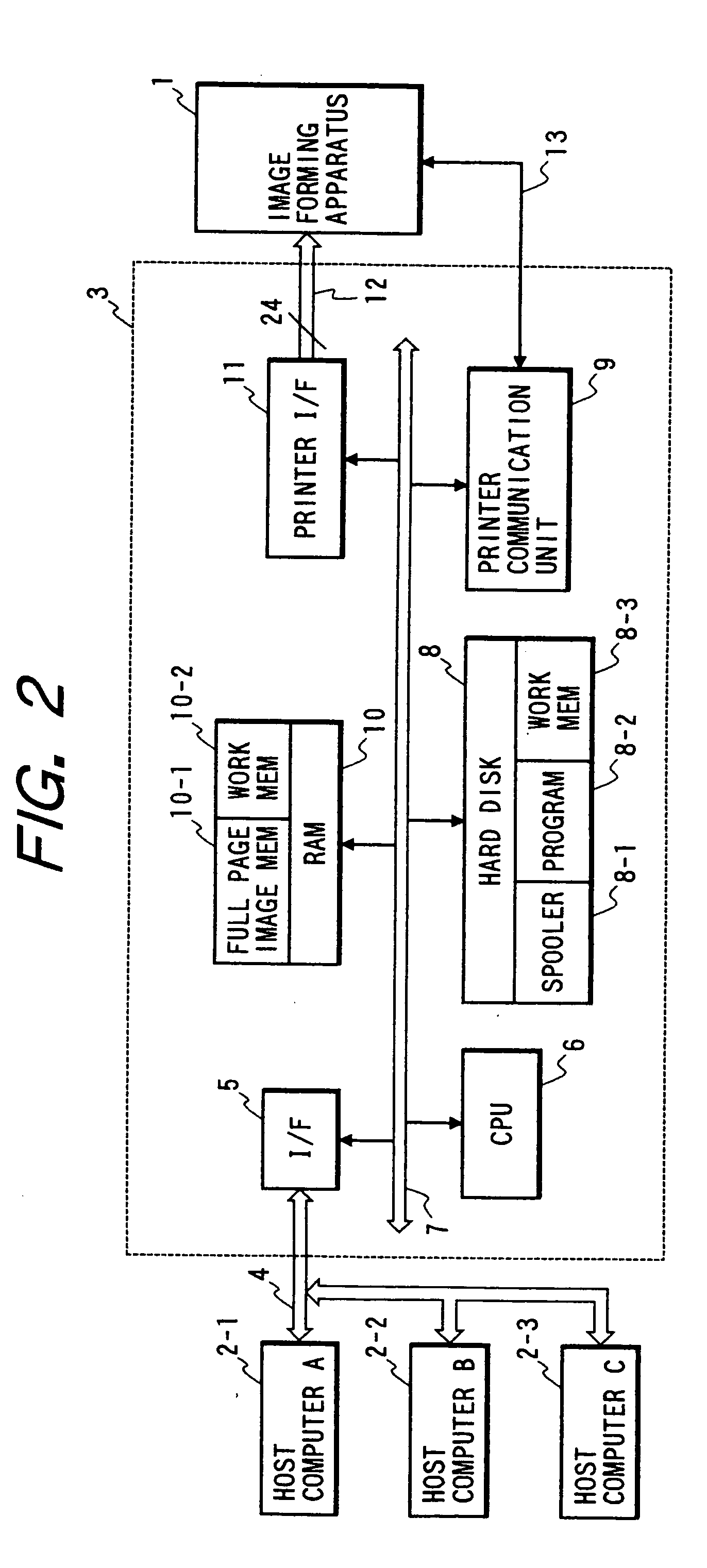
[0042]FIG. 2 is a block diagram which shows an image formation system comprising an image processing apparatus 3 and an image forming apparatus 1, which deal with the color PDL in accordance with a first embodiment of the present invention.

[0043] As shown in FIG. 2, host computers 2-1, 2-2, and 2-3 and an image processing apparatus 3 are connected through a network 4. The PDL data that have been transferred from the host computers through the network 4 and an external interface circuit 5 are held once on a spooler area 8-1 on a hard disk 8 by means of a CPU 6. Then, the PDL data read out from the spooler area 8-1 are developed into the raster image data, which are written on a full-page image memory 10-1 in a RAM 10. The image data thus developed are read out from the full-page image memory 10-1 and transferred to an image forming apparatus 1 by way of a printer interface circuit 11 for the formation of images. The program area 8-2 on the hard disk 8 is use...

second embodiment

[0080] (Reducing Sheet Consumption)

[0081] In accordance with the first embodiment, a job joint is designated using the JDL job. For a second embodiment, however, a structure is arranged to automatically designate a job joint if jobs satisfy a certain condition. Here, the description of the same portions as those of the first embodiment will be omitted. In conjunction with FIG. 14, FIG. 15, and FIG. 16, the description will be made of the portions that differ from the first embodiment.

[0082] The second embodiment thus structured is aimed at reducing the consumption of sheets. Even when there is no immediate need for any printed-out sheets, it may sometimes desirable to have the sources of print out readily available at hand. Each job of the kind is put together for printing in the mode of 4-in-1 or the like in order to reduce the sheet consumption.

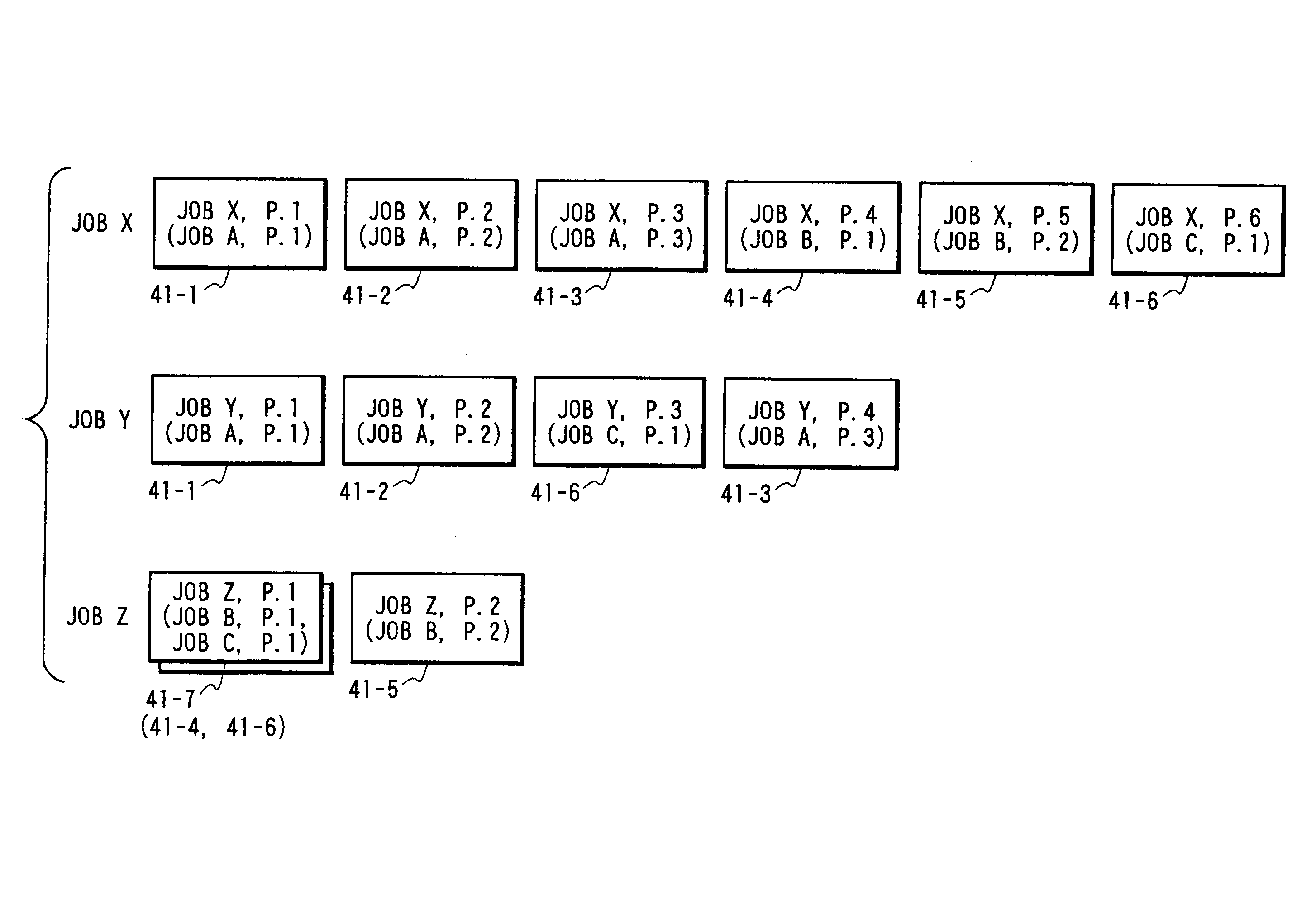
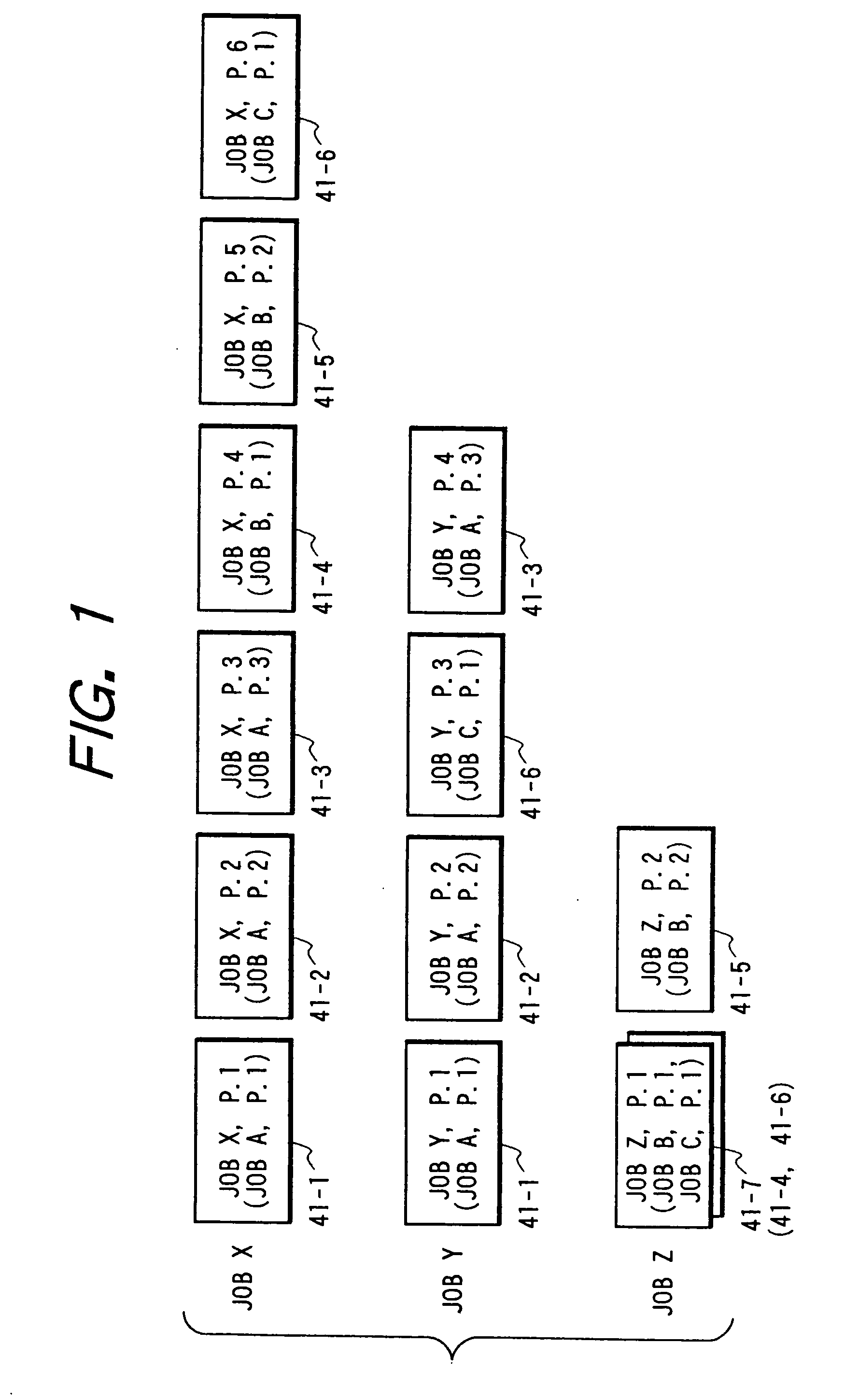
[0083]FIG. 14 is a view which illustrates queues arranged in the spooler in accordance with the second embodiment. As in the first embod...


PUM


Abstract

An apparatus for controlling image processing comprises means for receiving printing jobs, means for spooling the jobs received, means for joining jobs to make a plurality of the printing jobs retained in the spooling means one printing job by joining them, and means for transferring the joined printing job to a printer side. With a structure thus arranged, the various processes, which have been applied per job in a conventional art, can be applied to a plurality of printing jobs as a whole by joining and regarding them as one job.

Description

BACKGROUND OF THE INVENTION [0001] 1. Field of the Invention [0002] The present invention relates to an apparatus for controlling image processing to control processing image data transferred from a host computer or the like. More particularly, the invention relates to an apparatus for controlling image processing that receives image data from a host computer or the like in the form of the PDL data described using the page description language (hereinafter referred to as the PDL), and relates also to a method for controlling processing images. [0003] 2. Related Background Art [0004] Conventionally, the printing operation has been executed per printing job in a printing system in which PDL data are received from a host computer or the like, and images are processed and transferred for the image formation thereof. A unit set by a user in printing a document using an application program on a host computer is, in general, defined as a printing job. Each of such printing jobs transferred...

Claims


Application Information

Patent Timeline
Patent Type & Authority Applications(United States)
IPC IPC(8): G06F3/12G06K15/00
CPCG06F3/1217G06F3/1263G06K2215/0011G06F3/1285G06K15/00G06F3/1284
Inventor KADOWAKI, TOSHIHIRO
Owner CANON KK
Why Eureka
Try Eureka