Load limiting structure for vehicle occupant restraint system

Inactive Publication Date: 2005-01-20
KEY SAFETY SYST
View PDF16 Cites 22 Cited by
  • Summary
  • Abstract
  • Description
  • Claims
  • Application Information

AI Technical Summary

Problems solved by technology

Moreover, in those patents a crush tube is provided, and is crushed by the piston as the piston moves in one direction in the fluid chamber, to further dissipate forces applied to the piston by a vehicle occupant restraint system.

Method used


Image

  • Load limiting structure for vehicle occupant restraint system
  • Load limiting structure for vehicle occupant restraint system
  • Load limiting structure for vehicle occupant restraint system

Examples


Embodiment Construction

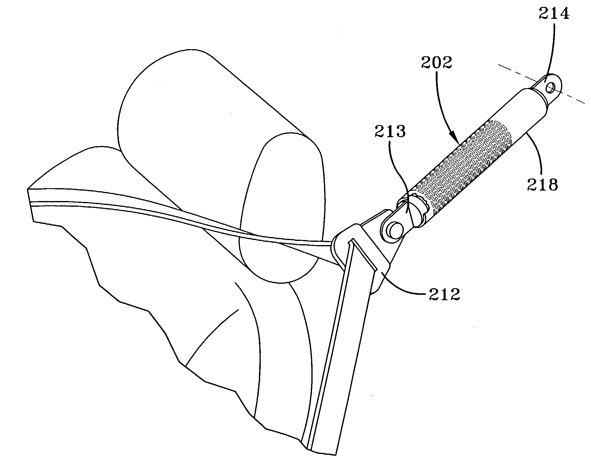
[0016] The present invention relates to a load-limiting device for a vehicle occupant restraint, which dissipates forces applied to a vehicle occupant during a crash. The principles of the present invention are applicable to different configurations for a vehicle occupant restraint, and are described below in connection with a belt that includes a lap belt and shoulder harness (which is often referred to as a three-point safety restraint system). It will be clear to those in the art that the principles of the invention are applicable to a variety of vehicle occupant restraints (e.g. front and rear seat belts, etc) and are applicable to vehicle occupant restraints anchored to various structural parts of a vehicle (e.g. a vehicle floor, B-pillar, vehicle seat, etc).

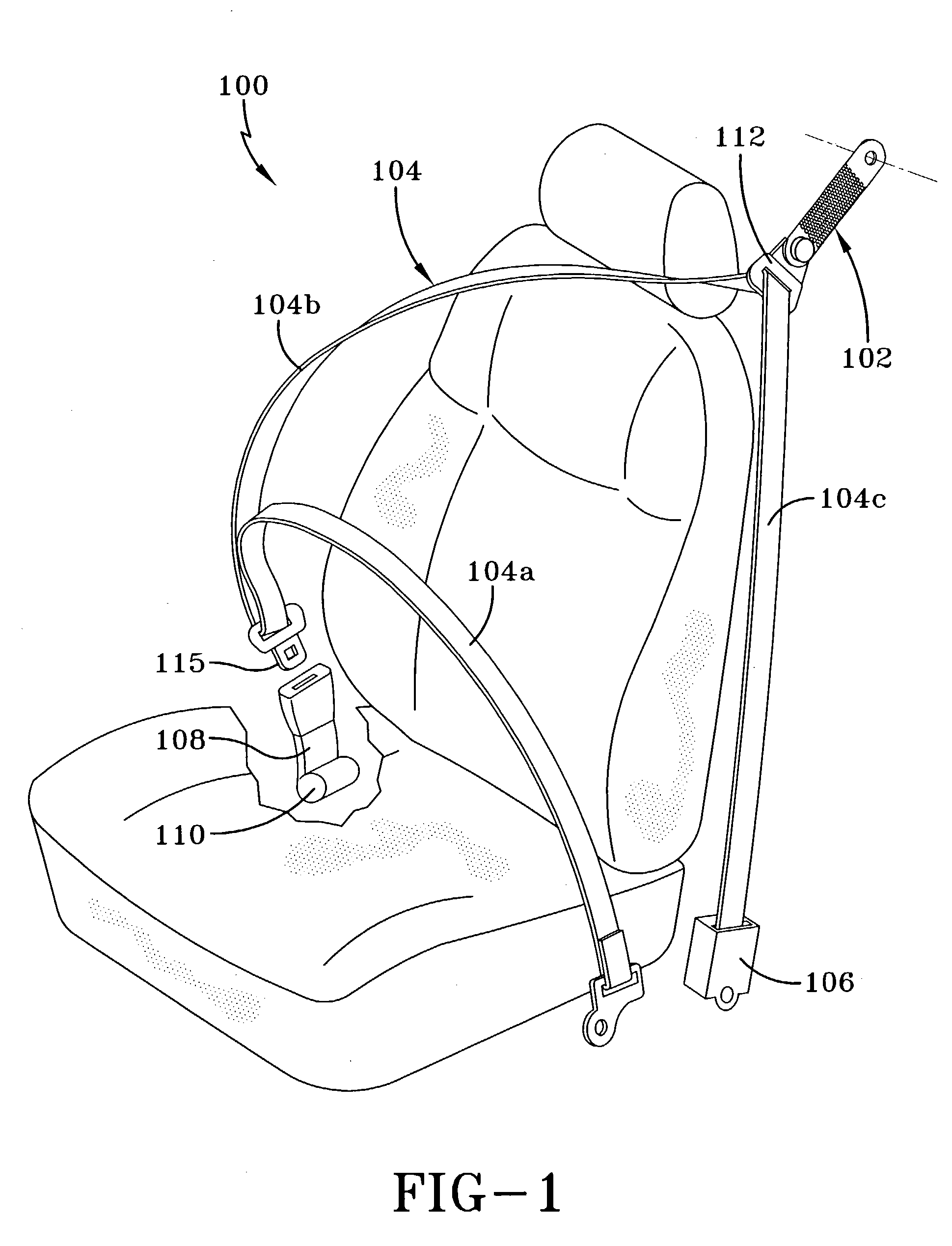
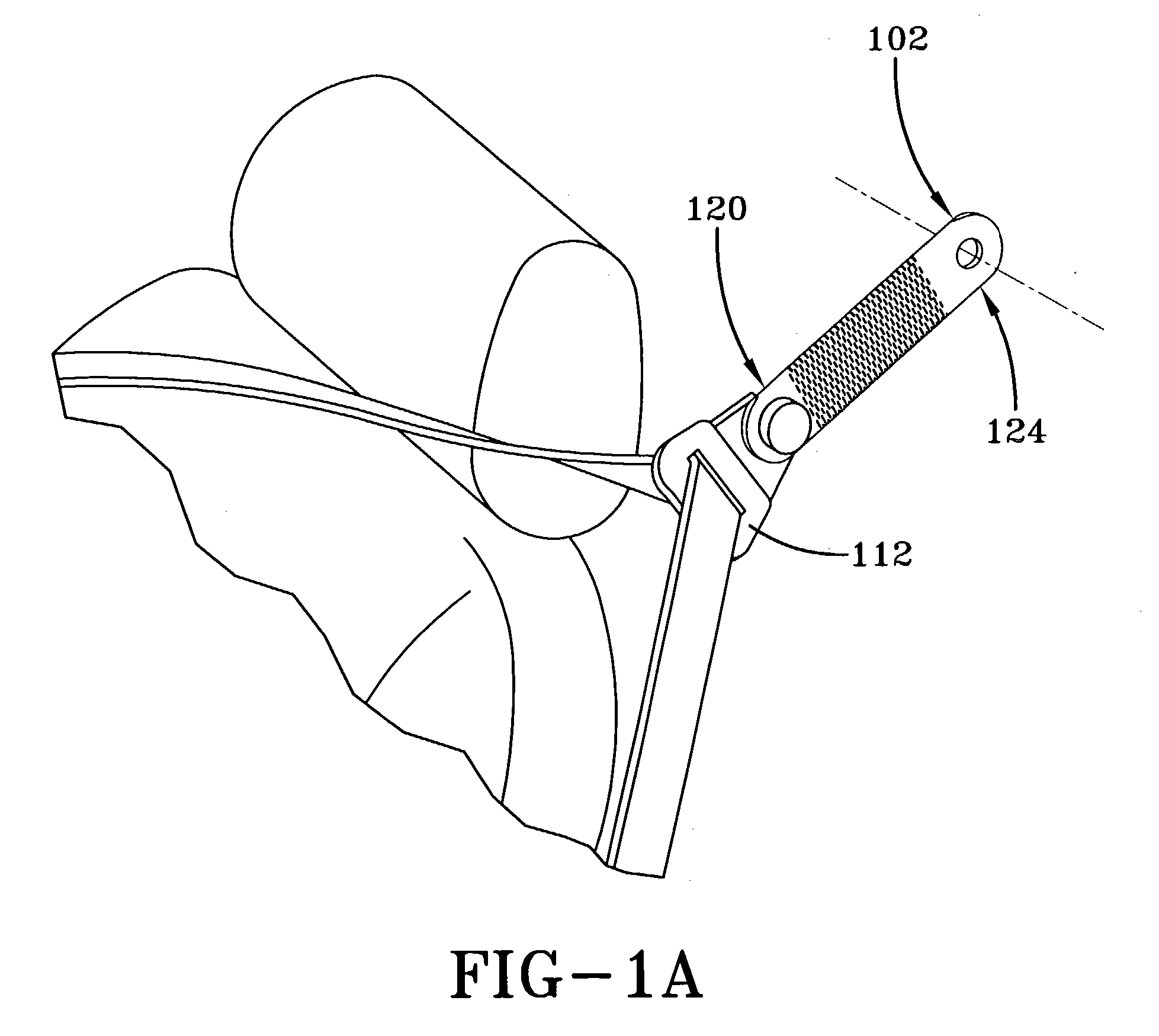
[0017]FIGS. 1 and 1A schematically illustrate a vehicle occupant restraint system 100, which incorporates a load-limiting device 102 according to the present invention. The vehicle occupant restraint system is belt 104 des...


PUM


Abstract

A new and useful load-limiting device for a vehicle occupant restraint is provided. The load-limiting device comprises a longitudinal, load-limiting member connected between the vehicle occupant restraint and an anchor point such as a vehicle seat or a structural part of the vehicle. The load-limiting member is configured to deform plastically to dissipate forces applied to the load-limiting member by the vehicle occupant during a crash. Moreover, according to the preferred embodiments, the design of the load-limiting member provides a new and useful form of plastic deformation to dissipate forces applied to the load-limiting member by the vehicle occupant restraint. Specifically, in one embodiment the load-limiting member comprises a deformable strip with a pattern of perforations disposed in staggered rows extending transverse to the strip. In another embodiment the load-limiting member comprises a deformable tube with a pattern of perforations disposed in staggered rings extending about the central axis of the tube. The configuration of the load-limiting member provides a plurality of beam like segments that deform progressively, and with bending beam characteristics, to dissipate forces applied to the load-limiting member by the vehicle occupant during a crash.

Description

FIELD OF THE INVENTION [0001] The present invention relates to a load limiting structure for a vehicle occupant restraint. BACKGROUND OF THE INVENTION [0002] A typical occupant restraint system for a vehicle comprises a belt (often comprising a lap belt component and a shoulder belt component) anchored to structural parts of the vehicle such as the floor, a pillar such as a B pillar or to a seat frame. Where the restraint system includes a shoulder belt portion (also referred to herein as a “shoulder harness”), the shoulder harness typically extends through a web guide that is coupled to a structural part of the vehicle such as the B-pillar or the seat frame. The restraint system further includes a retractor, often called an “ELR or emergency locking retractor”, which is designed to take up or provide a controlled amount of slack in the belt system when the belt system has been fitted about a vehicle occupant. The retractor allows payout of belt (typically the shoulder belt) in resp...

Claims


Application Information

Patent Timeline
Patent Type & Authority Applications(United States)
IPC IPC(8): B60R22/28
CPCB60R2022/286B60R22/28
Inventor SCHULZ, KURT
Owner KEY SAFETY SYST
Why Eureka
Try Eureka