
Floating conductor pad for antenna performance stabilization and noise reduction

a conductor pad and antenna technology, applied in the direction of antenna couplings, radiating element structural forms, resonance antennas, etc., can solve the problems of mobile device use difficulty, and the operating characteristics of embedded antennas tend to be affected by other device components, so as to reduce the effect of transceiver component variations and the effect of reducing the effect of device components on antenna variations

Inactive Publication Date: 2005-01-27
MALIKIE INNOVATIONS LTD
View PDF73 Cites 77 Cited by
  • Summary
  • Abstract
  • Description
  • Claims
  • Application Information

AI Technical Summary

Benefits of technology

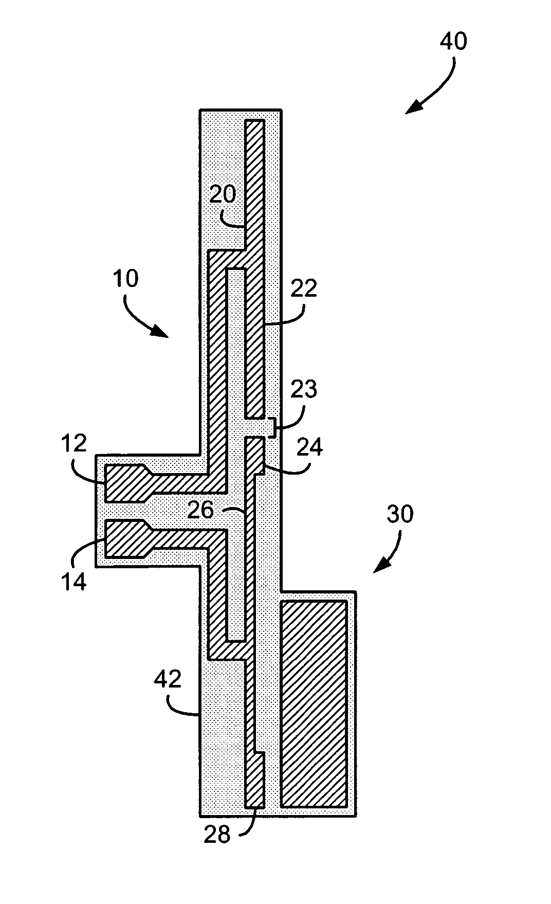
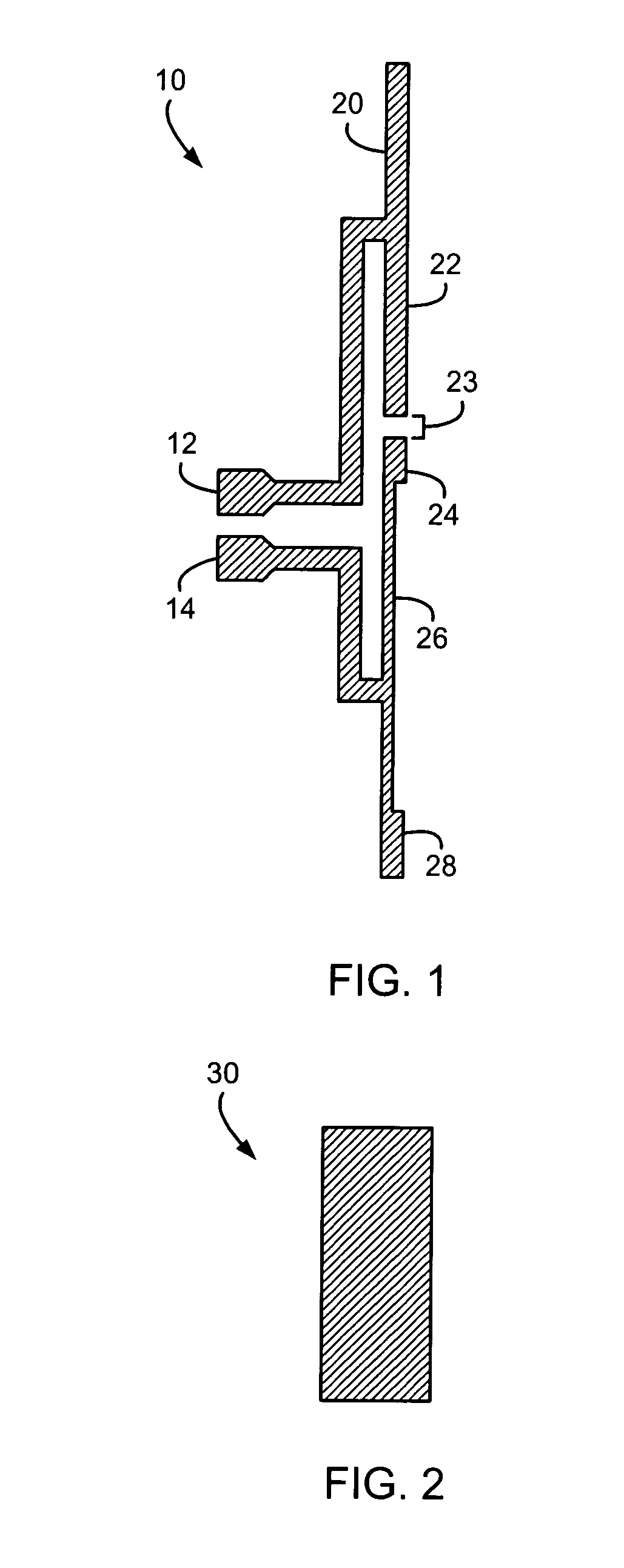
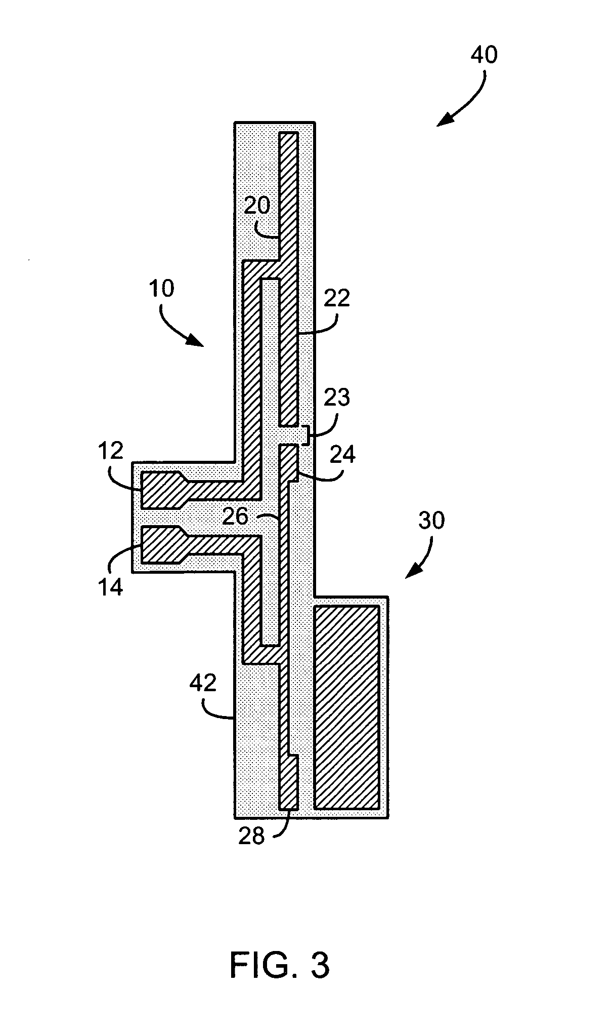
[0004] An antenna for a wireless communication device having a plurality of device components, according to another aspect of the invention, comprises an antenna element and a floating conductor pad positioned adjacent the antenna element and configured to couple to the antenna element, to thereby reduce effects of variations in the device components on the antenna.
[0005] In accordance with another aspect of the invention, a wireless mobile communication device comprises a transceiver incorporating transceiver components, an antenna connected to the transceiver, and a floating conductor pad positioned adjacent the antenna and configured to couple to the antenna to reduce effects of variations in the transceiver components on the antenna.

Problems solved by technology

Although external antennas may physically interfere with the surroundings of a mobile device and make a mobile device difficult to use, particularly in limited-space environments, embedded antennas present fewer such challenges.
However, operating characteristics of embedded antennas tend to be affected by other device components.

Method used


Image

  • Floating conductor pad for antenna performance stabilization and noise reduction
  • Floating conductor pad for antenna performance stabilization and noise reduction
  • Floating conductor pad for antenna performance stabilization and noise reduction

Examples


Embodiment Construction

[0018] Antennas are typically designed to operate in one or more particular operating frequency bands. Multi-band antennas are often implemented with multiple antenna elements tuned to different operating frequency bands. For example, suitably tuned separate antenna elements enable a multiple-element antenna for operation at the Global System for Mobile Communications (GSM) and General Packet Radio Service (GPRS) frequency bands at approximately 900 MHz and 1800 MHz or 1900 MHz, or at the Code Division Multiple Access (CDMA) frequency bands at approximately 800 MHz and 1900 MHz. Where desired operating frequency bands are relatively closely spaced, within 100-200 MHz, or sometimes where the bands are harmonically related, a single antenna element may be configured for multi-band operation. In a GPRS mobile device, for example, operation in all three frequency bands may be desired to support communications in networks in different countries or regions using a common antenna structure...


PUM


Abstract

An antenna in a wireless mobile communication device is often sensitive to its operating environment, such that variations in other device components typically affect performance of the antenna. A floating conductor pad comprising a patch of conductive material is configured to be positioned adjacent the antenna to couple to the antenna. The floating conductor pad thereby has a dominant effect on the antenna in the operating environment. This reduces the effects of variations in the other device components on the antenna. Effective selection of the dimensions and location of the floating conductor pad can also cancel noise generated by the other device components from de-sensitizing communications circuitry in a wireless mobile communication device.

Description

FIELD OF THE INVENTION [0001] This invention relates generally to the field of antennas. More specifically, a floating conductor pad is provided that is particularly well-suited for use in conjunction with antennas in wireless communication devices such as Personal Digital Assistants (PDAs), cellular telephones, and wireless two-way email communication devices. BACKGROUND OF THE INVENTION [0002] Mobile communication devices (“mobile devices”) having various antenna structures are known. Many different types of antennas for mobile devices are also known, including helix, “inverted F”, folded dipole, and retractable antenna structures. Helix and retractable antennas are typically installed outside a mobile device, and inverted F and folded dipole antennas are typically embedded inside a mobile device case or housing. Generally, embedded antennas are preferred over external antennas for mobile devices for mechanical and ergonomic reasons. Embedded antennas are protected by the mobile d...

Claims


Application Information

Patent Timeline
IPC IPC(8): H01Q1/24H01Q1/38H01Q1/52H01Q19/00
CPCH01Q1/243H01Q19/005H01Q1/526H01Q1/38
Inventor MAN, YING TONGPHILLIPS, ROBERT W.QI, YIHONGJARMUSZEWSKI, PERRYROOKE, DAVID JOHN
Owner MALIKIE INNOVATIONS LTD
Learn More