Linear motion guide device

Inactive Publication Date: 2005-01-27
ABBA LINEAR TECH
View PDF7 Cites 13 Cited by
  • Summary
  • Abstract
  • Description
  • Claims
  • Application Information

AI Technical Summary

Benefits of technology

[0014] The primary objective of the present invention is to provide a linear motion guide device having an improved ball or roller guiding mechanis

Problems solved by technology

However, when two objects are slidably engaged or coupled with each other, no suitable linear motion guide devices have been provided for facilitating the sliding movements between the two slidable objects.
However, each of the endless and sliding type roller connectors includes a number of balls or rollers that are required to be coupled or connected together with a complicated connection portion such that the typical linear motion guide devices each comprising a complicated configuration that may not be easily assembled, and that may cost much for manufacturing purposes.
However, for stably and smoothly retaining the balls or rollers within the endless roller-circulation paths, a number of parts or elements are required to be manufactured and assembled, to allow the balls or rollers to be easily assembl

Method used


Image

  • Linear motion guide device
  • Linear motion guide device
  • Linear motion guide device

Examples


Example

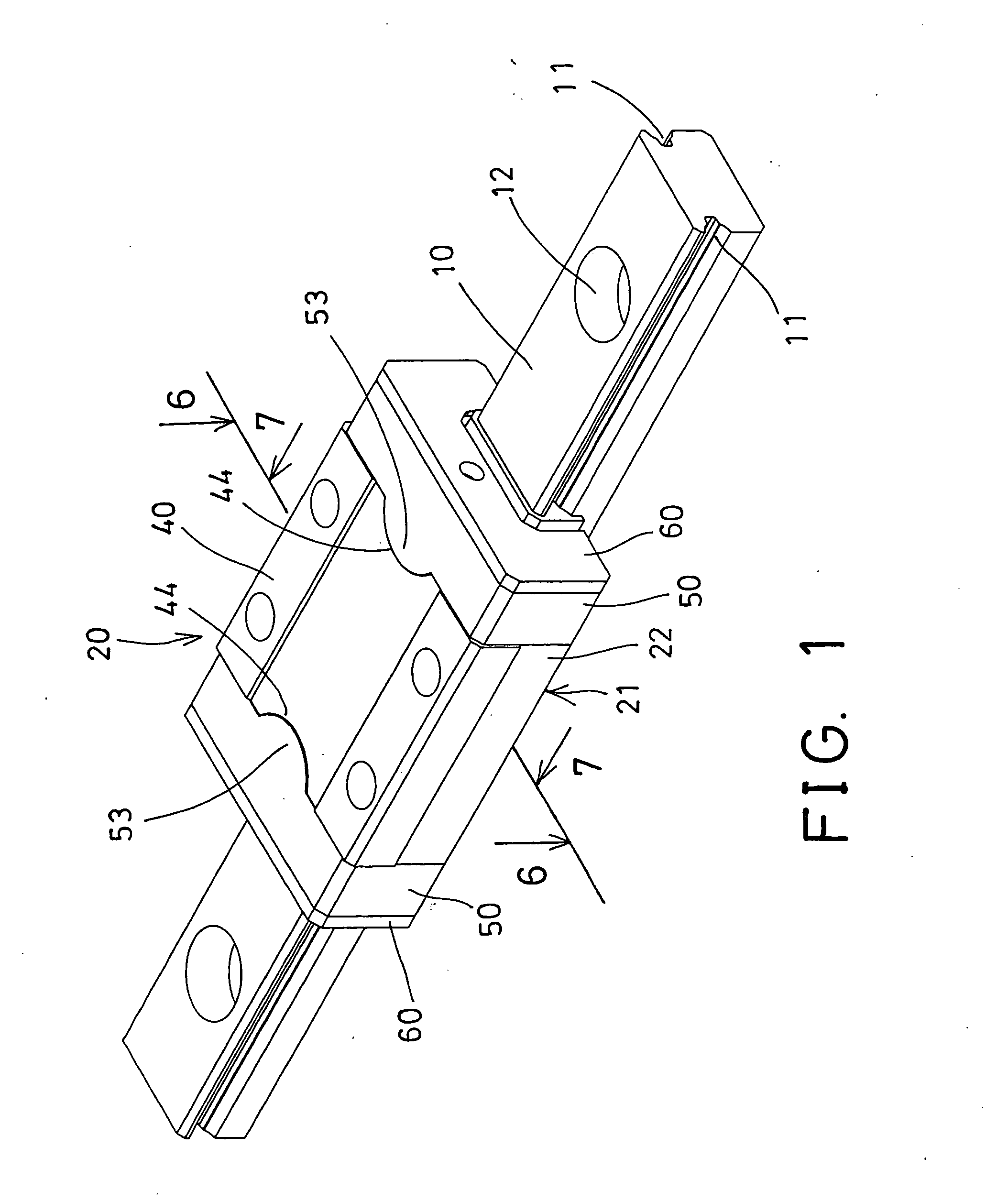
[0030] Referring to the drawings, and initially to FIG. 1, a linear motion guide device in accordance with the present invention is provided for being disposed in various kinds of apparatus, such as computers, machines, etc., for facilitating sliding movements between two or more relative slidable objects.

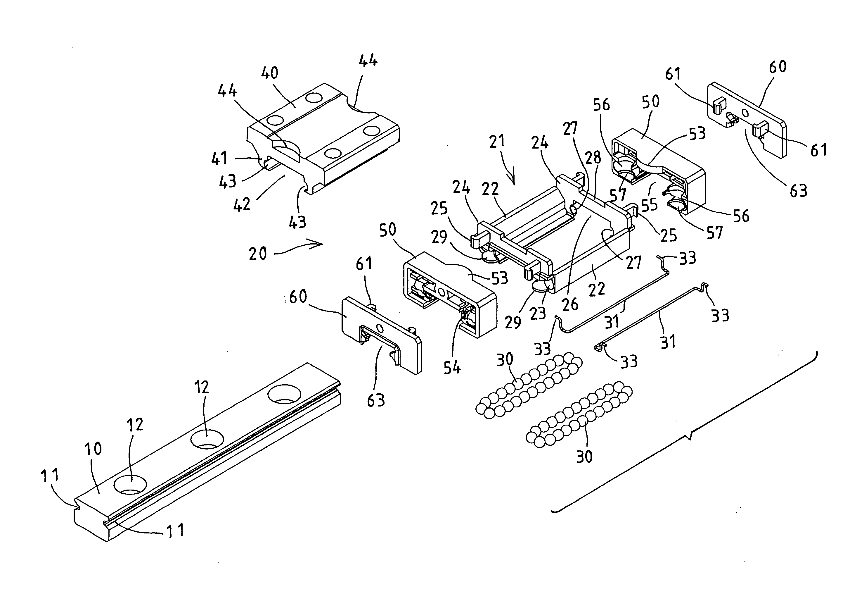
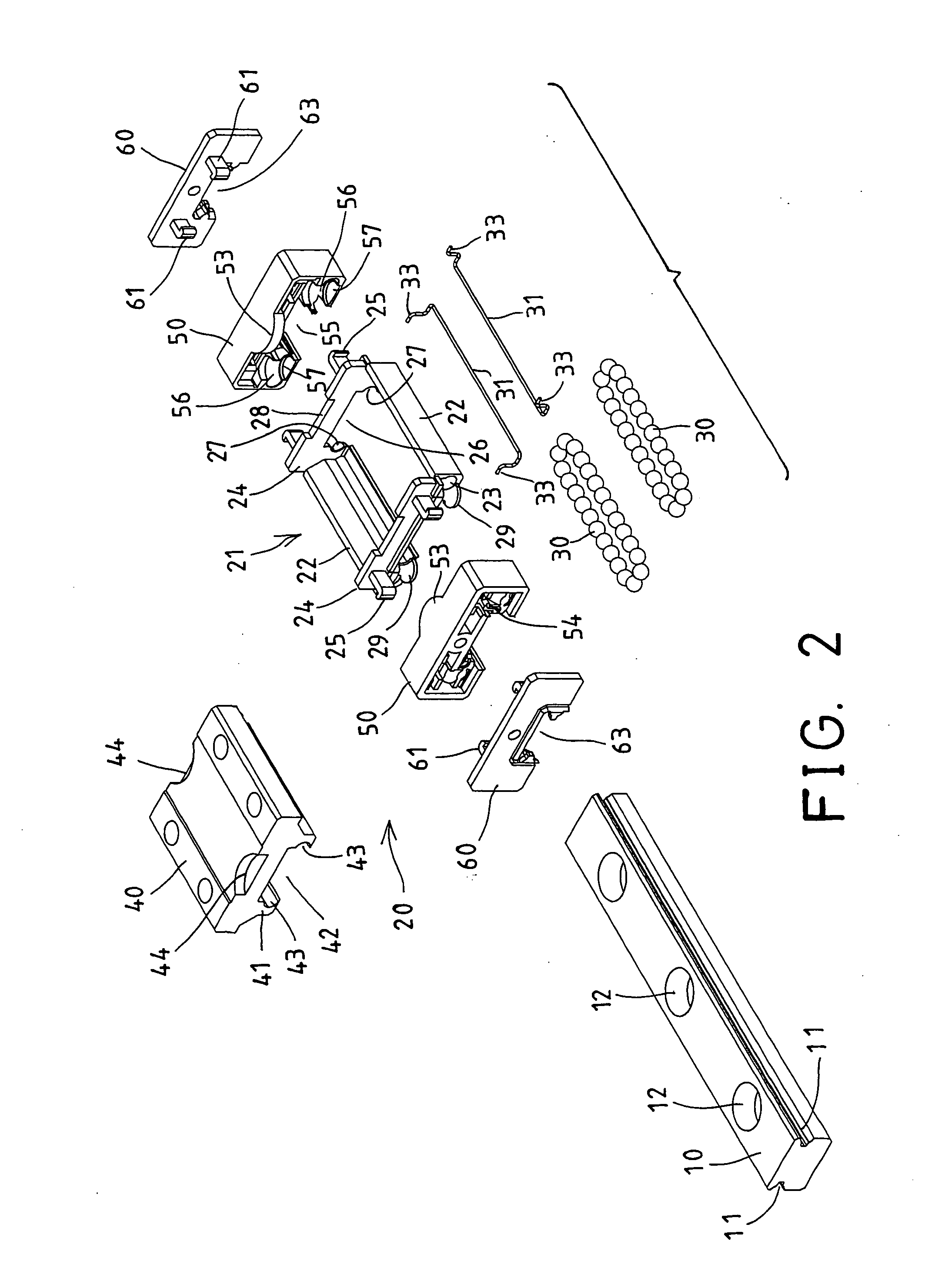
[0031] For example, as shown in FIGS. 2 and 3, the linear motion guide device comprises an elongate member 10, such as an elongate track 10 including one or two sides each having a longitudinal depression 11 formed therein for slidably receiving rotary members 30, such as balls, rollers, etc. therein. The elongate track 10 may include one or more holes 12 formed therein for securing to the apparatus or objects with such as fasteners.

[0032] A sliding member 20 is to be slidably engaged onto and movable along the elongate track 10, and includes a frame 21 having a pair of side panels 22 and two end plates 24 secured between the ends of the side panels 22 respectively, in order to f...


PUM


Abstract

A linear motion guide device includes a casing having two beams disposed between two end plates and two side panels of a frame, each beam has a longitudinal slot, two stops are secured to the end plates with latches, and each has a projection engaged with the casing, to anchor the casing in the frame, and each has two indentations communicating with the longitudinal passages of the side panels and the longitudinal slots of the beams of the casing, to form two endless roller-circulation paths, and to receive rotary members. Two pressing members include two ends secured to the stops, and engaged with the rotary members, to retain the stops and the frame together.

Description

[0001] The present invention is a continuation-in-part of U.S. patent application Ser. No. 10 / 355,908, filed 29 Jan. 2003, to be abandoned.BACKGROUND OF THE INVENTION [0002] 1. Field of the Invention [0003] The present invention relates to a linear motion guide device, and more particularly to a linear motion guide device having improved ball or roller guiding mechanisms for facilitating the sliding movements between objects. [0004] 2. Description of the Prior Art [0005] Typical bearings are provided and engaged between two rotary members, for facilitating the rotational movements between the two rotary or sliding members. [0006] However, when two objects are slidably engaged or coupled with each other, no suitable linear motion guide devices have been provided for facilitating the sliding movements between the two slidable objects. [0007] U.S. Pat. No. 6,305,846 to Michioka et al., U.S. Pat. No. 6,390,678 to Shirai, and U.S. Pat. No. 6,652,146 to Lee disclose three of the typical l...

Claims


Application Information

Patent Timeline
IPC IPC(8): F16C29/06F16C43/04
CPCF16C29/0607F16C43/04F16C29/0657F16C29/0609
Inventor LEE, MAO TUWANG, CHIN HSIANG
Owner ABBA LINEAR TECH
Why Eureka
Try Eureka