Handgrip for Handlebar

Inactive Publication Date: 2011-03-24
UNION IND
View PDF10 Cites 0 Cited by
  • Summary
  • Abstract
  • Description
  • Claims
  • Application Information

AI Technical Summary

Benefits of technology

[0005]Therefore, the object of the present invention is to provide a handgri

Problems solved by technology

Although the conventional handgrip can achieve its intended purpose, after a period of use, the handgrip will become loose

Method used


Image

  • Handgrip for Handlebar
  • Handgrip for Handlebar
  • Handgrip for Handlebar

Examples


Example

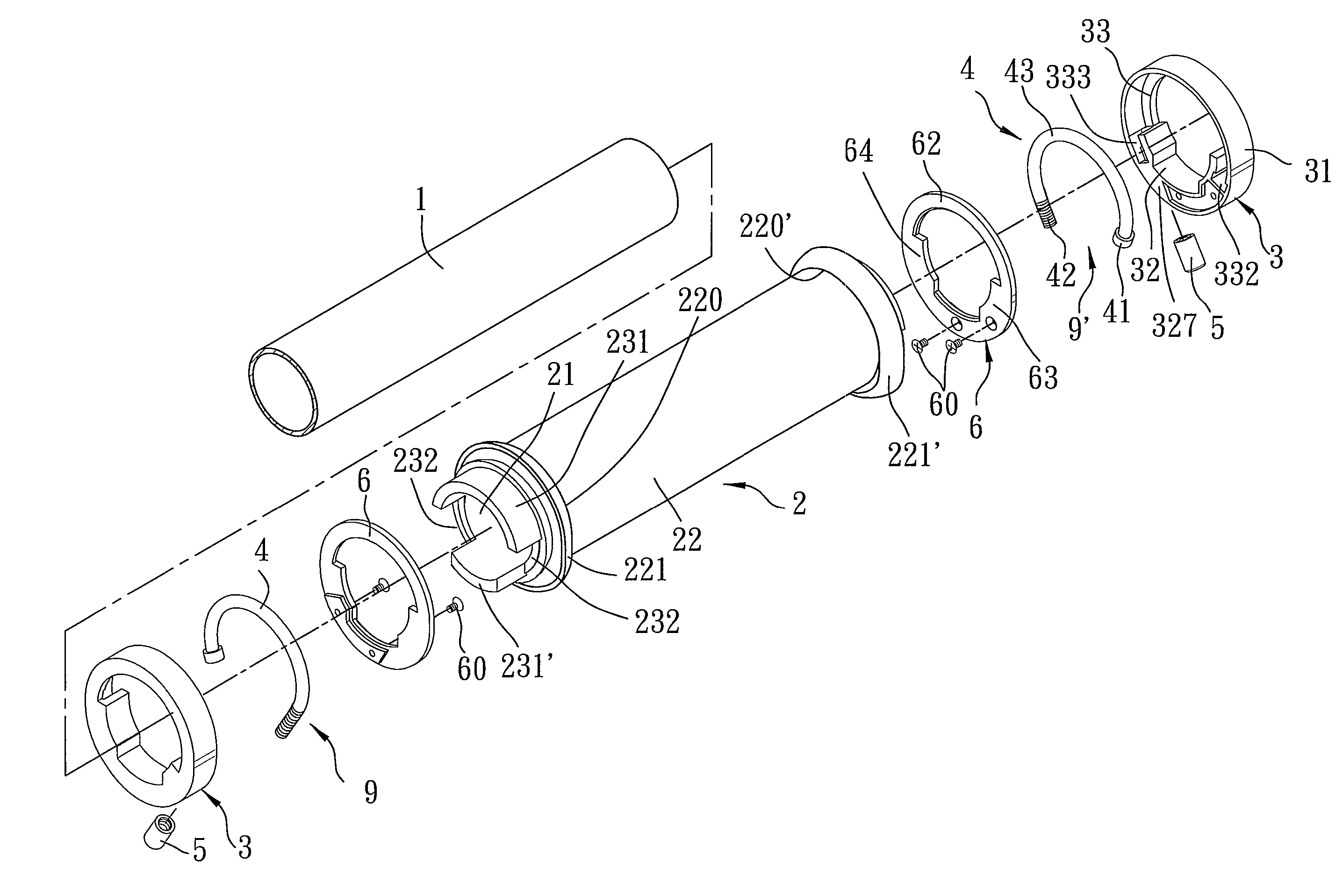
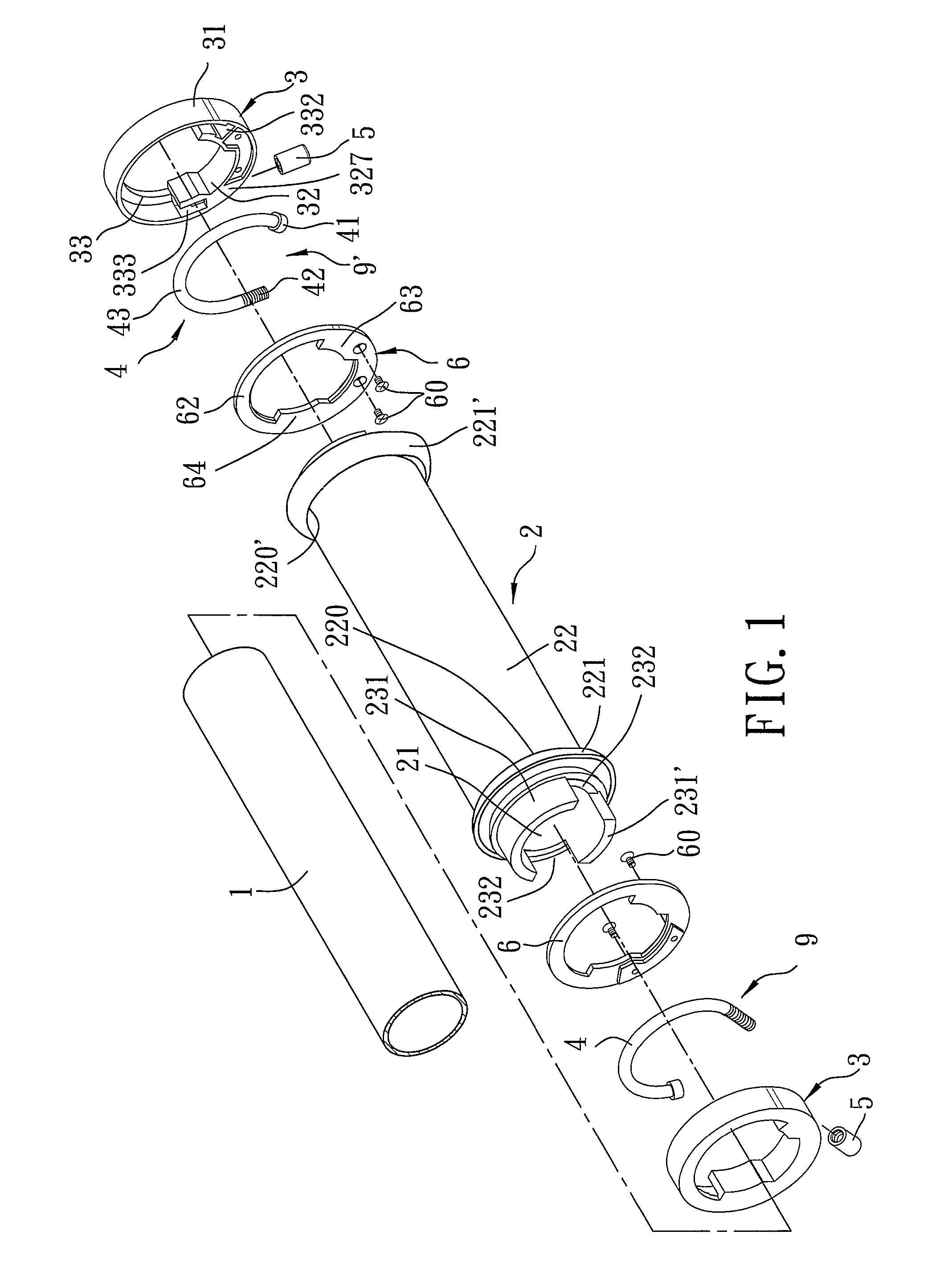
[0012]Referring to FIGS. 1 to 4, a handgrip according to the preferred embodiment of the present invention is adapted to be installed detachably on a handlebar 1, and is shown to comprise a tubular grip body 2, and first and second fastening units 9, 9′.

[0013]The tubular grip body 2 is adapted to be sleeved on the handlebar 1, and includes an outer tube 22 having opposite annular first and second ends 220, 220′, and an inner tube 21 inserted fittingly into the outer tube 22 and having at least two angularly spaced-apart resilient clamp portions 231, 231′ projecting outwardly and axially from a corresponding one of the first and second ends 220, 220′ (only the clamp portions 231, 231′ that project outwardly, oppositely, and axially from the first end 220 are visible in FIG. 1), and two angularly spaced-apart cutout portions 232 each formed between two adjacent ones of the clamp portions 231, 231′. Each of the first and second ends 220, 220′ has an annular flange 221, 221′ projecting ...


PUM


Abstract

A handgrip includes a tubular grip body having at least two angularly spaced-apart resilient clamp portions projecting outwardly and axially from an annular end thereof, a substantially U-shaped rod member having a bight portion, and non-threaded head and threaded end portions, and a sleeve ring sleeved around the resilient clamp portions and having first and second curved retaining grooves receiving respectively the resilient clamp portions, a head-receiving groove section receiving the non-threaded head portion, and a guide groove section receiving the threaded end portion. A nut member is disposed outwardly of the guide groove section, and engages threadedly the threaded end portion. The nut member pulls the threaded end portion when tightened so that the bight portion pushes one of the resilient clamp portions toward the other resilient clamp portion.

Description

BACKGROUND OF THE INVENTION[0001]1. Field of the Invention[0002]This invention relates to a handgrip for a handlebar.[0003]2. Description of the Related Art[0004]A conventional handgrip generally assembled on a handlebar of a vehicle or a movable instrument is soft, and has an anti-slip function. The conventional handgrip is usually made of a resilient material, such as rubber, and is formed as a single body. The handgrip is sleeved fittingly on the handlebar. Although the conventional handgrip can achieve its intended purpose, after a period of use, the handgrip will become loose and unstable due to material fatigue, so that the handgrip and the handlebar are likely to rotate relative to each other.SUMMARY OF THE INVENTION[0005]Therefore, the object of the present invention is to provide a handgrip that can be secured stably and assembled quickly and easily to a handlebar.[0006]According to this invention, a handgrip for a handlebar comprises a tubular grip body and a fastening uni...

Claims


Application Information

Patent Timeline
IPC IPC(8): B25G1/10
CPCB25G3/20B62K21/26Y10T16/476Y10T16/469Y10T16/466
Inventor CHEN, MING-CHANG
Owner UNION IND
Why Eureka
Try Eureka