Eureka AIR delivers breakthrough ideas for toughest innovation challenges, trusted by R&D personnel around the world.

Electrical switching apparatus and adjustable carrier assembly therefor

Active Publication Date: 2010-10-14
EATON INTELLIGENT POWER LIMITED
View PDF11 Cites 4 Cited by
  • Summary
  • Abstract
  • Description
  • Claims
  • Application Information

AI Technical Summary

Benefits of technology

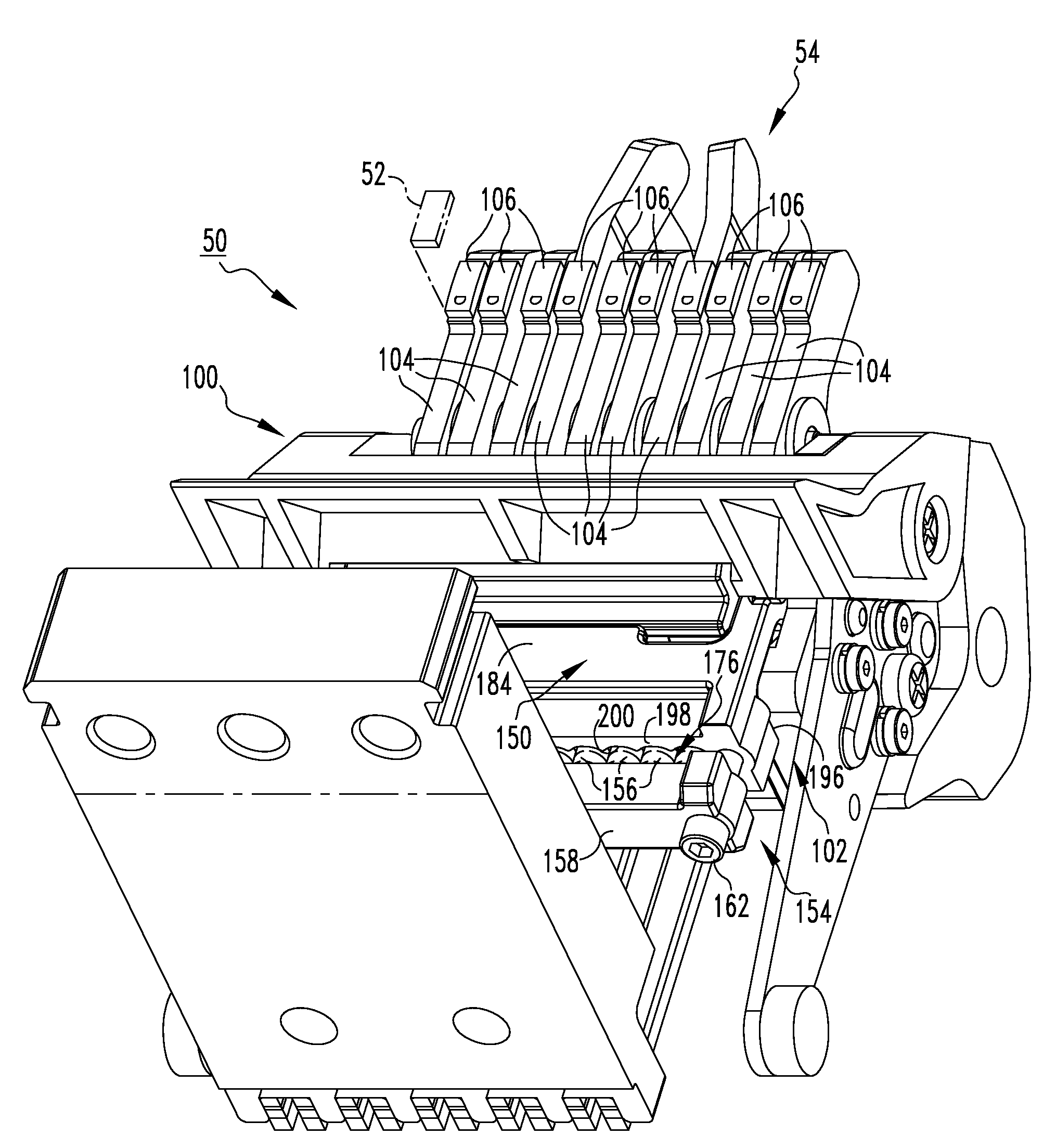
[0011]These needs and others are met by embodiments of the disclosed concept, which are directed to an adjustable carrier assembly for the movable contact assembly of an electrical switching apparatus, such as a circuit breaker. Among other benefits, the adjustable nature of the carrier assembly enables it to be relatively quickly and easily assembled and adjusted to be within requisite or desired engineering specification limits (e.g., for blow off force).
[0013]The adjustment mechanism may comprise an elongated member and a number of fasteners, wherein the fasteners fasten the elongated member to the first carrier member of the carrier body. The fasteners may be structured to be tightened to move the elongated member toward the first carrier member, thereby increasing the bias force, and to be loosened to move the elongated member away from the first carrier member, thereby decreasing the bias force.

Problems solved by technology

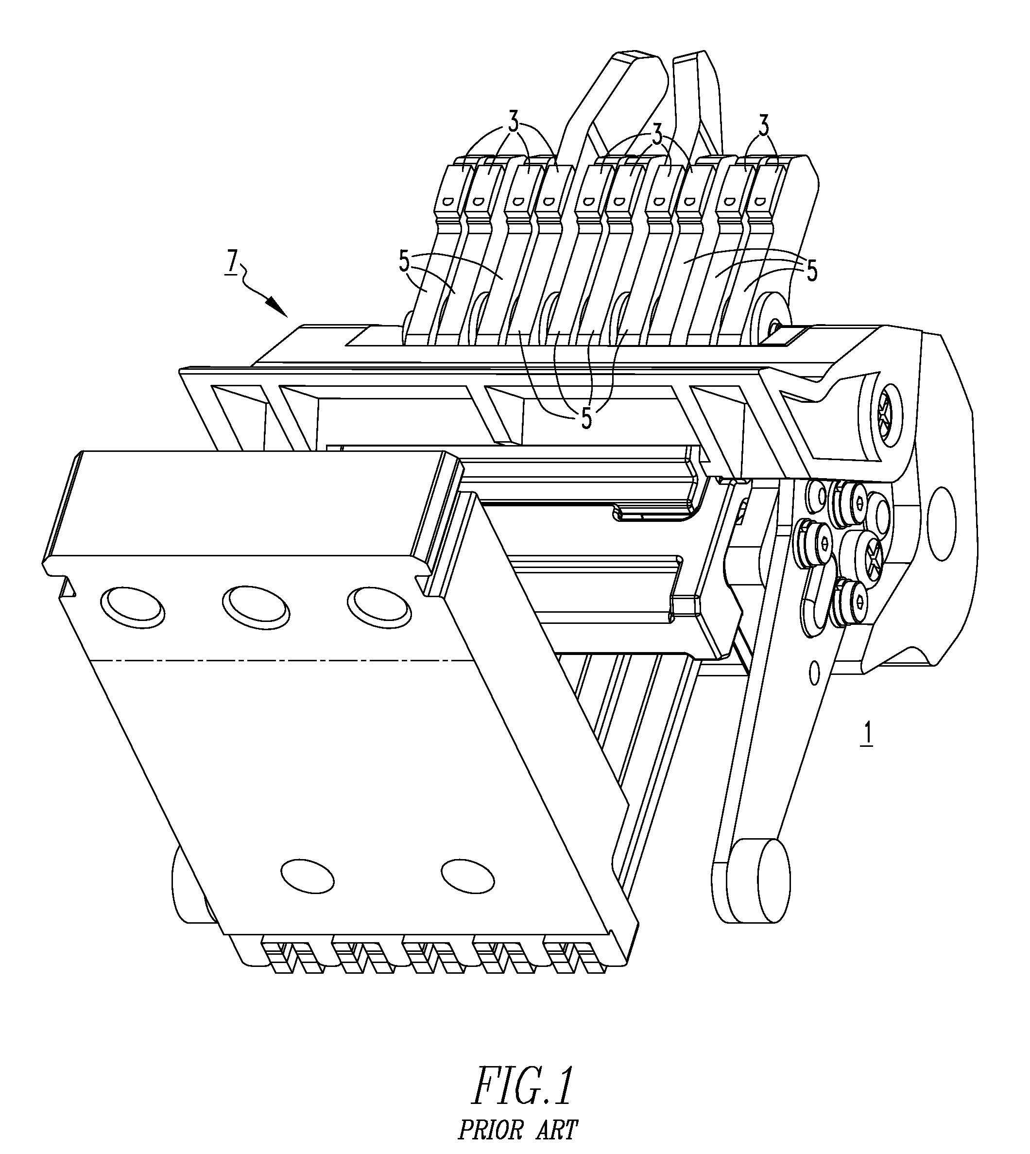
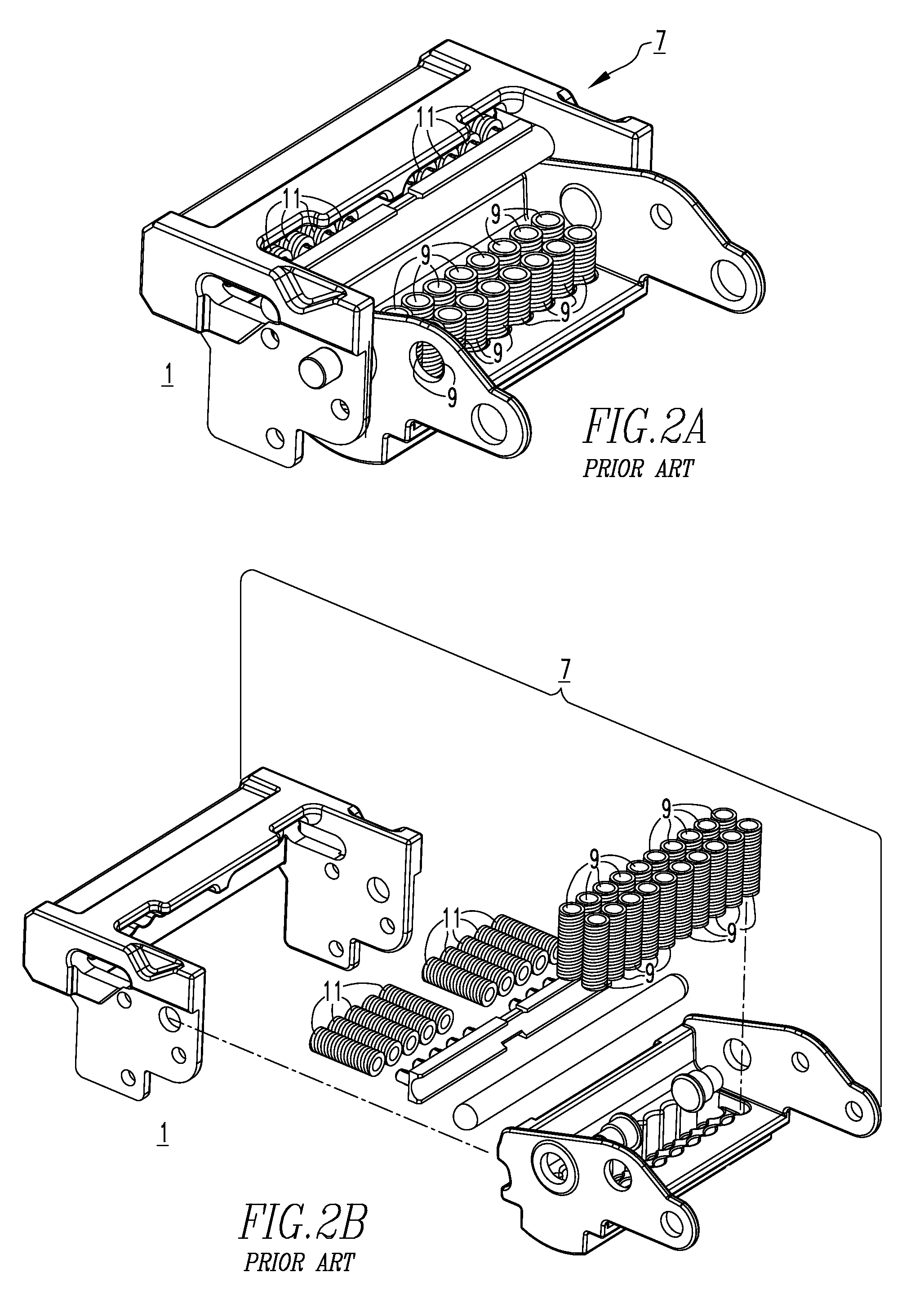
Among other disadvantages, such carrier assembly designs include numerous parts and are relatively difficult to assemble.
Improper alignment results in inconsistent spring force, and a lower than desired withstand rating for the circuit breaker.
Such carrier assembly designs are also sensitive to dimensional variations among the various components of the carrier assembly 7 which, on one hand, can result in undesirably low blow off forces (e.g., nuisance blow where unintended electrical disconnection occurs) and, on the other hand, can contribute to undesirably high blow off forces potentially leading to higher than desired current being let through the circuit breaker and causing damage to the circuit breaker.

Method used


Image

  • Electrical switching apparatus and adjustable carrier assembly therefor
  • Electrical switching apparatus and adjustable carrier assembly therefor
  • Electrical switching apparatus and adjustable carrier assembly therefor

Examples


Embodiment Construction

[0024]Directional phrases used herein, such as, for example, left, right, beneath, under and derivatives thereof, relate to the orientation of the elements shown in the drawings and are not limiting upon the claims unless expressly recited therein.

[0025]As employed herein, the term “blow off force” refers to the electromagnetic force that tends to open electrical contact between separable electrical contacts (e.g., stationary contacts; movable contacts). Under certain electrical fault conditions (e.g., without limitation, current overloads; short circuits; other fault conditions), an opposing bias force is surpassed by the blow off force, resulting in the movable contact(s) blowing off of the corresponding stationary contact(s) to break the flow of electric current therethrough.

[0026]The term “blow open force” means the same as the term “blow off force”. For example, in switching apparatus incorporating current limiting contact structures, the separable contacts are commonly arrange...


PUM


Abstract

An adjustable carrier assembly is provided for an electrical switching apparatus such as, for example, a circuit breaker. The adjustable carrier assembly includes a carrier body having a first carrier member and a second carrier member pivotably coupled to the first carrier member. An adjustment mechanism is coupled to the carrier body, and a plurality of springs is disposed between the adjustment mechanism and the second carrier member. The springs apply a bias force on the second carrier member, and the adjustment mechanism is adjustable with respect to the carrier body in order to adjust the bias force.

Description

CROSS-REFERENCE TO RELATED APPLICATION[0001]This application is related to commonly assigned, concurrently filed:[0002]U.S. patent application Ser. No. ______, filed ______, 2009, entitled “ELECTRICAL SWITCHING APPARATUS, AND CARRIER ASSEMBLY AND SPRING GUIDE THEREFOR” (Attorney Docket No. 08-EDP-204).BACKGROUND[0003]1. Field[0004]The disclosed concept relates generally to electrical switching apparatus and, more particularly, to electrical switching apparatus, such as circuit breakers. The disclosed concept also relates to carrier assemblies for electrical switching apparatus.[0005]2. Background Information[0006]Electrical switching apparatus, such as circuit breakers, provide protection for electrical systems from electrical fault conditions such as, for example, current overloads, short circuits, abnormal voltage and other fault conditions. Typically, circuit breakers include an operating mechanism which opens electrical contact assemblies to interrupt the flow of current through...

Claims


Application Information

Patent Timeline
IPC IPC(8): H01H1/22
CPCH01H1/30H01H71/74H01H1/34
Inventor KAPPLES, LAWRENCE JOSEPHTURNER, DAVID CURTISMCAFEE, MARK ALLEN
Owner EATON INTELLIGENT POWER LIMITED
Why Eureka
Eureka Blog
Learn More