Connector having an improved effect of preventing an unlocking lever from being damaged

Active Publication Date: 2005-01-27
JAPAN AVIATION ELECTRONICS IND LTD
View PDF4 Cites 4 Cited by
  • Summary
  • Abstract
  • Description
  • Claims
  • Application Information

AI Technical Summary

Benefits of technology

[0006] It is therefore an object of the present invention to provide a connector which is compact and is capable of protecting an u

Problems solved by technology

However, in case where the operating portion is applied with a load in a direction other than the predetermined direction

Method used


Image

  • Connector having an improved effect of preventing an unlocking lever from being damaged
  • Connector having an improved effect of preventing an unlocking lever from being damaged
  • Connector having an improved effect of preventing an unlocking lever from being damaged

Examples


Example

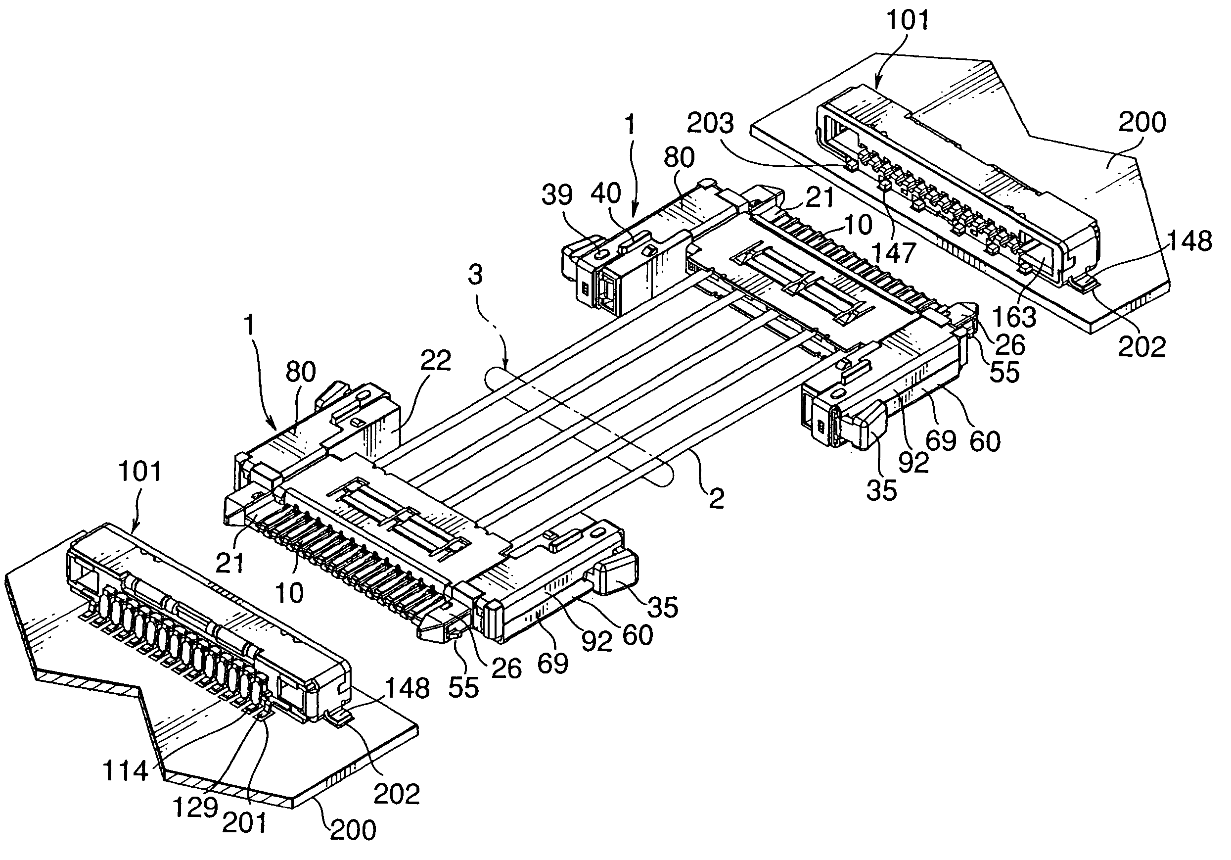
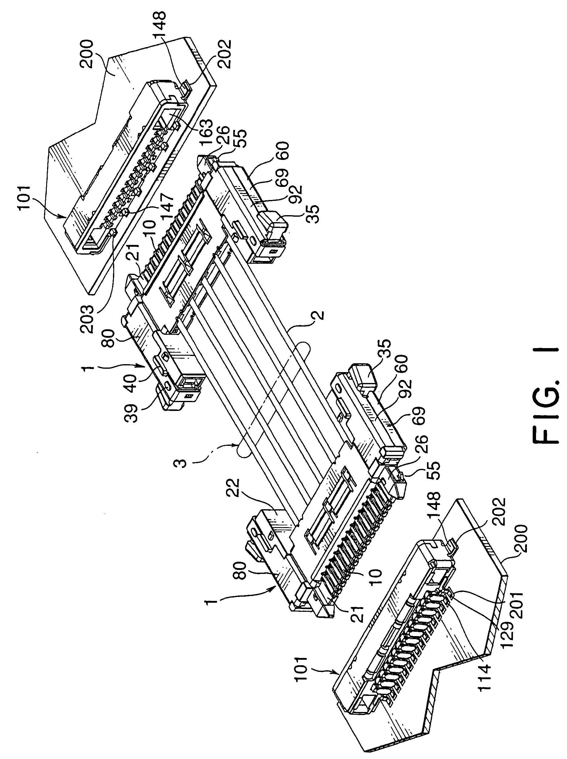
[0025] Referring to FIG. 1, description will be made of a connection apparatus according to one embodiment of the present invention.

[0026] The connection apparatus illustrated in the figure serves to electrically connect two circuit boards 200 equipped in various apparatuses. Two cable connectors 1 are connected by a plurality of cables 2 to form a cable harness 3. On each of the circuit boards 200, a board connector 101 is mounted. When the cable connectors 1 are fitted to the board connectors 101, respectively, the boards 200 are connected to each other.

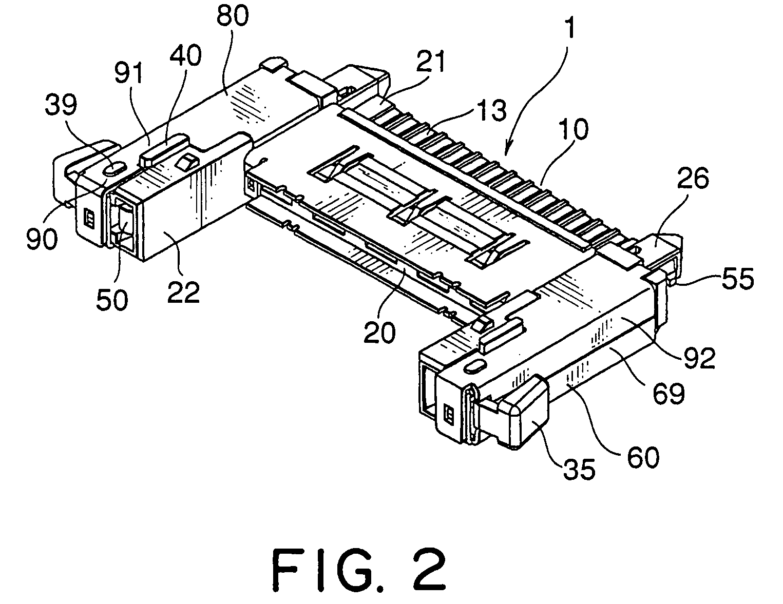
[0027] Referring to FIGS. 2 and 3 in addition to FIG. 1, the cable connector 1 will be described.

[0028] The cable connector 1 comprises a plurality of cable contacts 10 having conductivity, a cable insulator 20 holding the cable contacts 10, a pair of lock springs 50, a lower shell 60, and an upper shell 80. Each of the cable contacts 10 is fabricated by press working a metal material and has a press-fit portion 11, an encroache...


PUM


Abstract

In a connector having a conductive contact held by an insulator, a lock spring is held by the insulator and adapted to lock a connected state with a mating connector. A conductive shell covers the contact and the insulator. A lever is disposed adjacent to the lock spring. The lever is adapted to operate the lock spring and surrounded by a lever protecting portion serving as an operation inhibiting portion which is for limiting an operating direction of the lever and prevents an excessive displacement of the lever.

Description

[0001] This application claims priority to prior Japanese application JP 2003-166570, the disclosure of which is incorporated herein by reference. BACKGROUND OF THE INVENTION [0002] This invention relates to a connector having a locking mechanism for locking a connected state with a mating connector. [0003] For example, a connector disclosed in Japanese Patent Application Publication (JP-A) No. H9-120864 comprises a connector body and a strain relief connected to the connector body. The strain relief comprises a holding portion faced to the connector body, a first arm portion extending from the holding portion, a locking claw disposed near a free end of the first arm portion and adapted to lock a connected state with a mating connector, a second arm portion extending from the free end of the first arm portion in a direction opposite to the first arm portion, and an operating portion formed at a free end of the second arm portion and adapted to operate the locking claw. The strain re...

Claims


Application Information

Patent Timeline
IPC IPC(8): H01R13/639H01R13/627H01R13/629H01R13/631H01R13/633H01R13/648H01R13/658
CPCH01R13/6275H01R13/629H01R12/707H01R13/65802H01R13/6335H01R13/6583H01R13/639
Inventor TAKAKU, MASAAKIKAMATA, KAZUSHIISHIDA, SHUUICHIKIMURA, AKIRA
Owner JAPAN AVIATION ELECTRONICS IND LTD
Why Eureka
Try Eureka