Eureka AIR delivers breakthrough ideas for toughest innovation challenges, trusted by R&D personnel around the world.

Ejecting apparatus of a tray-type disk drive

a technology of ejecting apparatus and tray, which is applied in the direction of data recording, carrier cover, instruments, etc., can solve the problems of inconvenient and time-consuming, and achieve the effect of efficient ejecting of the disk-receiver

Inactive Publication Date: 2005-01-27
BENQ CORP
View PDF18 Cites 11 Cited by
  • Summary
  • Abstract
  • Description
  • Claims
  • Application Information

AI Technical Summary

Benefits of technology

The invention is an ejecting apparatus for a tray-type disk drive that efficiently ejects the disk-receiver without the need for a rod search. The apparatus includes a driving device, front faceplate, and rod. The rod is connected to the driving device through a swivel pivot, and can be rotated to align with or lie flat on the front faceplate. A spring is used to return the rod back to its original position. The apparatus also includes a light-emitting device that displays the operation status of the disk drive, with the rod and pushing rod being pervious to light. The technical effect of the invention is to provide an efficient and convenient way to eject disk-receivers from tray-type disk drives.

Problems solved by technology

It could be inconvenient and time wasting.

Method used


Image

  • Ejecting apparatus of a tray-type disk drive
  • Ejecting apparatus of a tray-type disk drive
  • Ejecting apparatus of a tray-type disk drive

Examples


Embodiment Construction

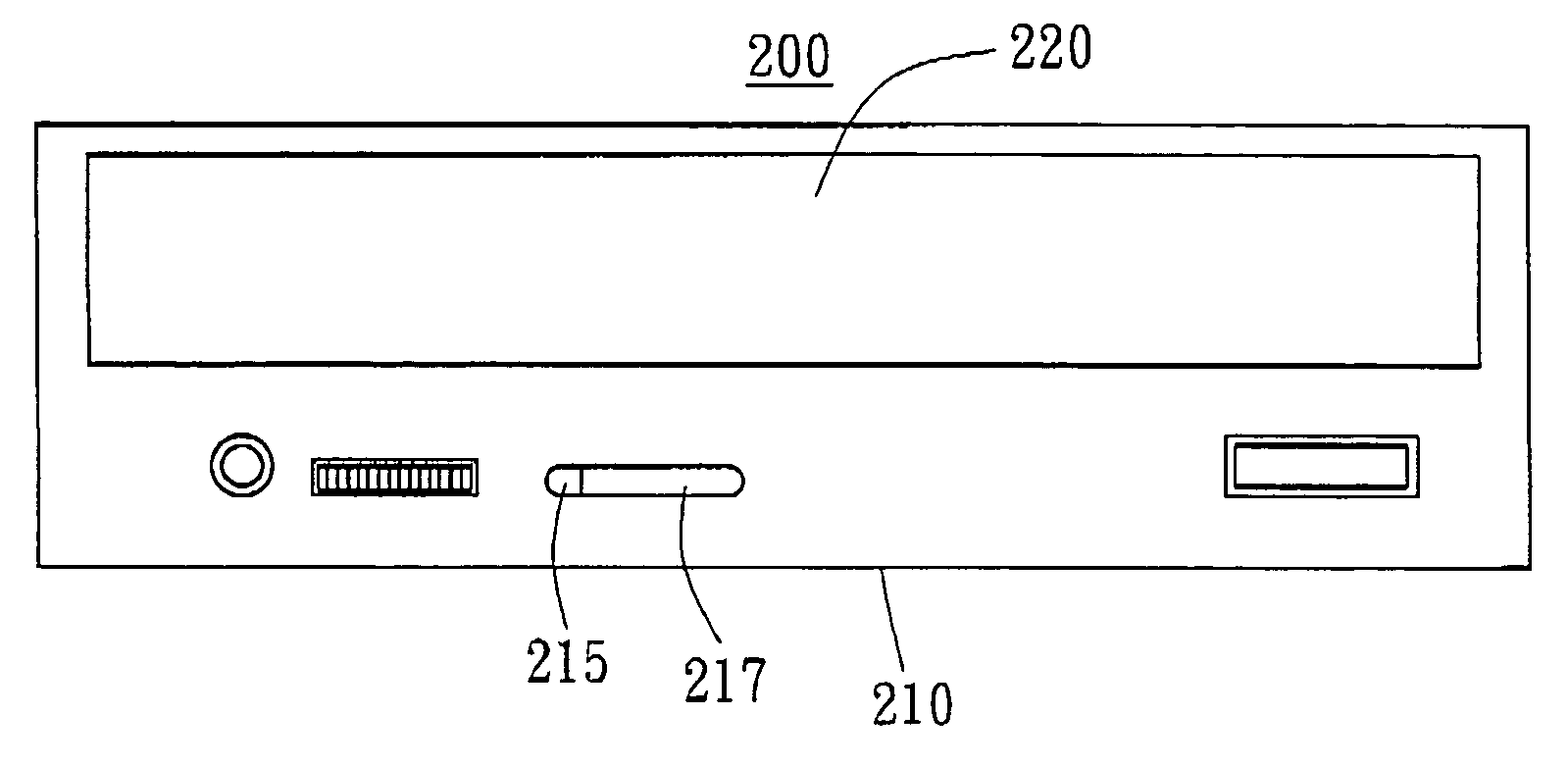
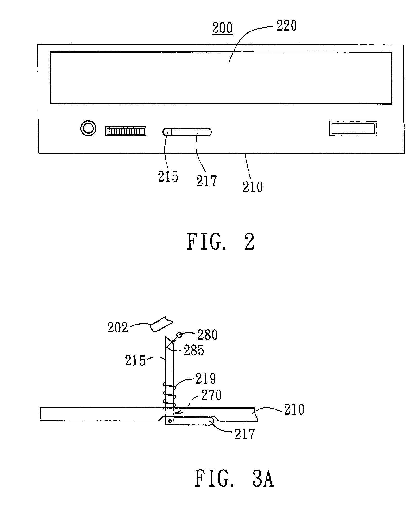
[0021] Please refer to FIG. 2, FIG. 3A, FIG. 3B, and FIG. 3C. FIG. 2 is a diagram of an ejecting apparatus according to the preferred embodiment of the invention. FIG. 3A is a vertical view of the front faceplate in FIG. 2. FIG. 3B is a diagram showing when the push rod of FIG. 3A is in an erected position. FIG. 3C is a diagram showing the push rod is pushed to touch the driving device.

[0022] The ejecting apparatus can be used in tray-type disk drive 200. The ejecting apparatus primarily includes a driving device 202, a front faceplate 210, a rod 215, a push rod 217, and a spring 219. By touching the driving device 202, which is located inside the tray-type disk drive 220, the disk tray 220 can be ejected from the tray-type disk drive 220.

[0023] The front faceplate 210 is installed at the front part of the tray-type disk drive 200 and the front faceplate 210 has an aperture 270 within which the rod 215 is installed. The head end of the rod 215 is located facing the driving device ...


PUM

PropertyMeasurementUnit
areaaaaaaaaaaa
volumeaaaaaaaaaa
timeaaaaaaaaaa

Abstract

An ejecting apparatus is applied to a tray-type disk drive with a disk tray. The ejecting apparatus has a driving device, a front faceplate, and a rod. The driving device is located within the tray-type disk drive. When the rod touches the driving device, the disk tray withdraws from the tray-type disk drive. The front faceplate is installed at the front part of the tray-type disk drive and the front faceplate has an aperture. The internal end of the rod is located facing the driving device and the external end of the rod protrudes through the aperture of the front faceplate. When the external end of the rod is pressed, the rod touches and activates the driving device so that the disk tray will be ejected from the tray-type disk drive.

Description

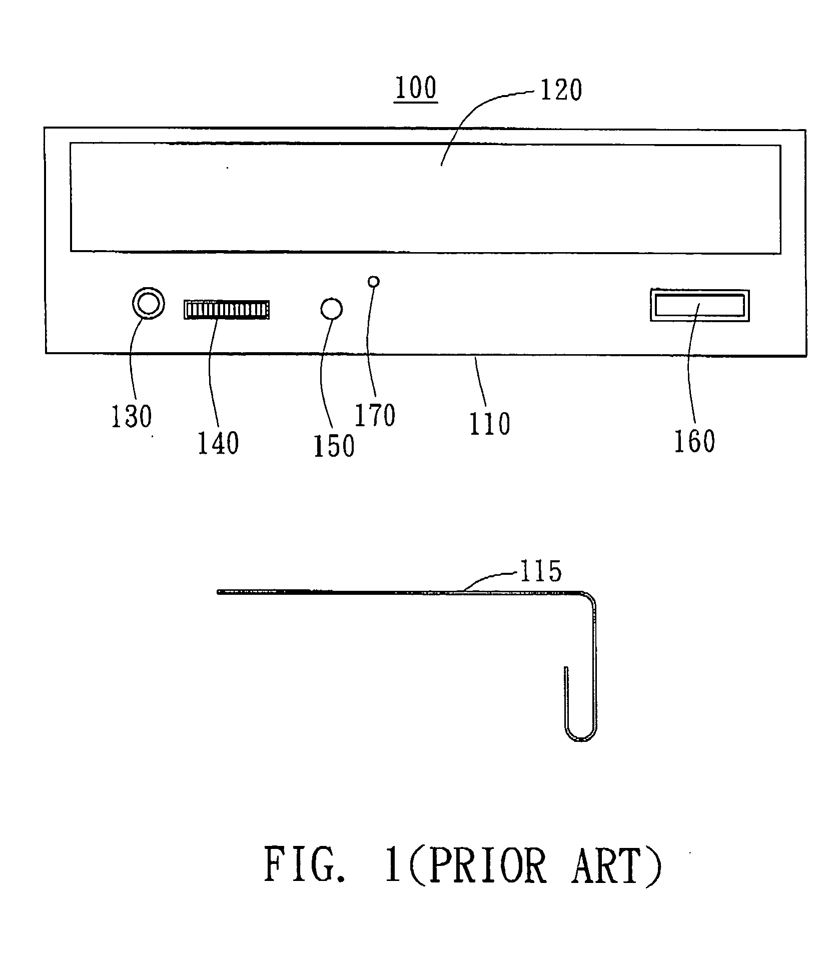
[0001] This application incorporates by reference Taiwan application Serial No. 92119895, filed Jul. 21, 2003, the subject matter of which is incorporated herein by reference. BACKGROUND OF THE INVENTION [0002] 1. Field of the Invention [0003] The invention relates in general to a disk-withdrawing apparatus, and more particularly to an ejecting apparatus that is applied in a tray-type disk drive. [0004] 2. Description of the Related Art [0005] Almost all the multimedia products are issued in the form of compact disks (CD) nowadays. Due to the popularity of consumable CDs, almost every computer has a disk drive. The significance of disk drive in the area of multimedia is very evident. [0006] Referring to FIG. 1, a diagram for a traditional ejecting apparatus is shown. The ejecting apparatus is used in tray-type disk drive 100. The ejecting apparatus has a driving device (located inside the tray-type disk drive 100, and is not shown in FIG. 1), a front faceplate 110, and a rod 115. [0...

Claims


Application Information

Patent Timeline
Patent Type & Authority Applications(United States)
IPC IPC(8): G11B17/04G11B33/02
CPCG11B33/027G11B17/056
Inventor LEE, MING-HUANG
Owner BENQ CORP
Why Eureka
Eureka Blog
Learn More