Developer storage container, image forming unit and image forming apparatus

Active Publication Date: 2012-01-12
OKI ELECTRIC IND CO LTD
View PDF23 Cites 4 Cited by
  • Summary
  • Abstract
  • Description
  • Claims
  • Application Information

AI Technical Summary

Benefits of technology

[0005]In an aspect of the present invention, it is intended to provide a developer storage container capable of efficiently ejectin

Problems solved by technology

However, in the conventional art, when a large amount of the developer is stored in the developer storage con

Method used


Image

  • Developer storage container, image forming unit and image forming apparatus
  • Developer storage container, image forming unit and image forming apparatus
  • Developer storage container, image forming unit and image forming apparatus

Examples


Example

First Embodiment

Configuration

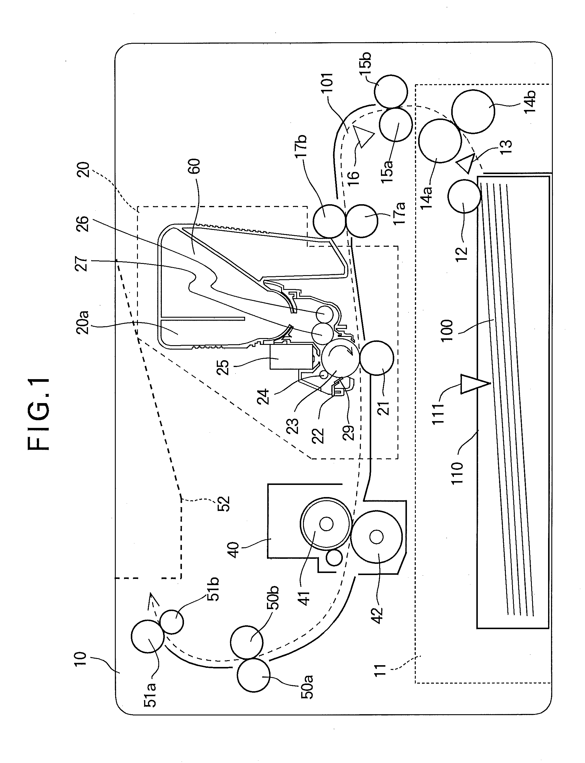
[0025]FIG. 1 is a schematic sectional view showing an image forming apparatus 10 according to the first embodiment of the present invention. The image forming apparatus 10 includes a feeding portion 11 that feeds a recording medium 100 (for example, a sheet) and a transport path 101 along which the recording medium 100 is transported. Along the transport path 101, the image forming apparatus 10 includes transport rollers 15a and 15b that transport the recording medium 100 along the transport path 101, a writing sensor 16 that detects a passage of a leading edge of the recording medium 100, and registration rollers 17a and 17b that correct a skew of the recording medium 100 and further transport the recording medium 100. The image forming apparatus 10 further includes an image forming portion 20 that forms a toner image (i.e., a developer image) on the recording medium 100, a fixing portion 40 that fixes the toner image to the recording medium 100, an eje...

Example

Second Embodiment

Configuration

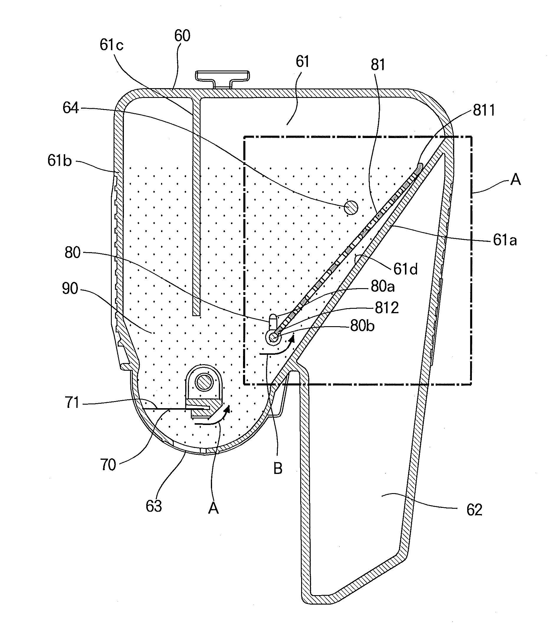
[0095]FIG. 9A is a plan view showing an agitating plate 81A of the second embodiment of the present invention.

[0096]The agitating plate 81A of the second embodiment is formed of ABS resin as in the first embodiment. Further, the agitating plate 81A has a substantially rectangular shape whose upper right corner and lower left and right corners are cut out as in the first embodiment.

[0097]The agitating plate 81A includes an upper end 811, a lower end 812, a left end 813 and a right end 814 respectively formed of ribs.

[0098]The agitating plate 81A further includes ribs 82A which are different from the ribs 82 of the agitating plate 81 of the first embodiment. The ribs 82A include four horizontal rib-parts 821 extending in the longitudinal direction of the agitating plate 81A, and three vertical rib-parts 822 extending in the widthwise direction of the agitating plate 81A. Among the three vertical rib-parts 822, the center vertical rib-part 822 extends betw...


PUM


Abstract

A developer storage container includes a developer storage portion in which a developer is stored, the developer storage portion having a wall, a rotating body rotatably provided in the developer storage portion, and an agitating plate that engages the rotating body and agitates the developer at least in the vicinity of the wall.

Description

BACKGROUND OF THE INVENTION[0001]The present invention relates to a developer storage container, an image forming unit and an image forming apparatus.[0002]An image forming apparatus includes a developer storage container such as a toner cartridge in which a developer such as a toner is stored. The developer storage container has an elongated opening at a bottom, through which the developer is ejected outside. In the developer storage container having a large capacity (i.e., a large inner space), an agitating member is provided for efficiently ejecting the developer from the developer storage container through the elongated opening.[0003]For example, Japanese Laid-open Patent Publication No. 2003-050505 discloses a toner cartridge having an agitating member and a toner remaining amount detecting mechanism therein.[0004]However, in the conventional art, when a large amount of the developer is stored in the developer storage container, it becomes difficult to efficiently eject the dev...

Claims


Application Information

Patent Timeline
IPC IPC(8): G03G15/08
CPCG03G15/0832G03G2215/0852G03G15/0855G03G15/0865G03G15/0889
Inventor FUJII, MASASHI
Owner OKI ELECTRIC IND CO LTD
Why Eureka
Try Eureka