Liquid-ejecting head, liquid-ejecting device, liquid-ejecting method, and ejection medium for liquid-ejecting head

a liquid ejection head and liquid ejection technology, which is applied in the field of liquid ejection, can solve the problems of low upper limit of operating temperature range, difference in print density between before and after extended recording, and inability to degrade inkjet heads. achieve stable ejection properties, wide operating temperature range, and suitable viscosity for ejection

Inactive Publication Date: 2008-10-23
SONY CORP
View PDF4 Cites 4 Cited by
  • Summary
  • Abstract
  • Description
  • Claims
  • Application Information

AI Technical Summary

Benefits of technology

[0028]Accordingly, it is desirable to provide a liquid-ejecting head, a liquid-ejecting device, a liquid-ejecting method, and an ejection medium for the liquid-ejecting head which constantly ensure high ejection stability by reducing the effects of changes in head temperature due to use environments on ink properties, particularly variations in the amount of ink droplets ejected and the direction in which the ink droplets are ejected, to simultaneously achieve improved recording quality and high-speed recording and provide a wider operating temperature range.
[0032]According to these embodiments, when a liquid ejection medium is used at normal temperatures above the freezing point, the heating means, which is unrelated to the ejection operation, generates heat to maintain the liquid cell at an appropriate temperature higher than the ambient temperature during standby for ejection. The heating means can therefore maintain the ejection medium, which is contained in the liquid cell, at a constant temperature higher than the ambient temperature irrespective of the ambient temperature during standby and ejection operation.
[0034]The ejection medium according to this embodiment exhibits ideal properties for use in the liquid-ejecting head, the liquid-ejecting device, and the liquid-ejecting method according to the embodiments described above. The ejection medium is not necessarily water, and may be, for example, an organic solvent or water containing an organic solvent. The ejection medium can be optimized for use in the liquid-ejecting head, the liquid-ejecting device, and the liquid-ejecting method according to the above embodiments by suitably adjusting the viscosity of the ejection medium, which is most closely related to temperature among various liquid properties.
[0036]The liquid-ejecting head, the liquid-ejecting device, and the liquid-ejecting method according to the above embodiments of the present invention maintain a liquid ejection medium contained in a liquid cell at a constant temperature during standby and ejection so that the ejection medium has viscosity suitable for ejection. The liquid-ejecting head, the liquid-ejecting device, and the liquid-ejecting method can therefore maintain stable ejection properties to prevent startup ejection failure immediately after power-up or in intermittent ejection, enables high-speed continuous recording with a wider operating temperature range, and can efficiently eject fine droplets or an ejection medium with high viscosity at normal temperature.
[0037]The ejection medium according to the embodiment of the present invention has viscosity suitable for ejection at the temperature of the liquid cell of a liquid-ejecting head. The ejection medium therefore exhibits preferred properties for use in the liquid-ejecting head, the liquid-ejecting device, and the liquid-ejecting method according to the above embodiments of the present invention, thus largely improving recording quality.

Problems solved by technology

These operations undesirably degrade the inkjet heads because the head temperature becomes excessively high after extended continuous recording.
On the other hand, the upper limit of the operating temperature range is low because the ink exhibits excessively low viscosity when the head temperature rises after, for example, extended continuous recording.
This leads to a difference in print density between before and after extended recording.
This problem is more serious near the upper and lower limits of the recording range of printing paper.
In low-temperature environments such as cold climates, particularly, the same amount of ink ejected as that at average temperature is difficult to ensure.
In addition, the direction in which the ink is ejected can vary and, more seriously, the ink can cause ejection defects.
In such cases, print defects such as white streaks and white spots appear in images printed on printing paper, thus degrading recording quality.
As a result, these types of inkjet heads exhibit poor ejection properties when suddenly driven from standby at low temperature.
In that case, the use of an ink with high viscosity, which can move less easily, results in thin print areas or temporal ejection failure at the beginning of recording.
In addition to the problem described above, line heads have a problem associated with small head units connected in line.
The production of a one-piece line head extending over the width of printing paper is not practical; a typical line head is composed of small head units arranged in line with the ends thereof connected.
The sharing, however, leads to temperature variations between the individual head units, and density variations and white streaks become serious particularly for thermal line heads.
This problem results from the fact that the temperatures of more frequently used head units rise while those of less frequently used head units remain at the ambient temperature.
As described above, inkjet printers undesirably have narrow operating temperature ranges due to the increase in ink viscosity in a low-temperature environment.
This problem has increasingly become serious with recent advances in the performance of inkjet printers.
On the other hand, the size reduction of nozzle holes for finer ink droplets leads to increased viscous drag of ink.
In that case, the increase in ink viscosity in a low-temperature environment becomes more serious irrespective of the type of ink ejection (thermal ejection, electrostatic ejection, or piezoelectric ejection) or the structure of inkjet heads (serial heads or line heads).
This approach, however, encounters another problem associated with thermal expansion.
The preliminary ejection, however, wastes a substantial amount of ink irrespective of recording on printing paper, thus increasing ink consumption and operating cost.
This method, however, takes much time before recording (first print).
The technique according to the publication, however, has difficulty in simultaneously achieving improved recording quality and high-speed recording to constantly ensure high ejection stability.
In addition, this technique undesirably complicates the overall system because special consideration is given to preheat the inkjet head only when the measured head temperature falls below the reference temperature.
Furthermore, this publication makes no disclosure of the extension of the operating temperature ranges of inkjet printers.

Method used


Image

  • Liquid-ejecting head, liquid-ejecting device, liquid-ejecting method, and ejection medium for liquid-ejecting head
  • Liquid-ejecting head, liquid-ejecting device, liquid-ejecting method, and ejection medium for liquid-ejecting head
  • Liquid-ejecting head, liquid-ejecting device, liquid-ejecting method, and ejection medium for liquid-ejecting head

Examples


Embodiment Construction

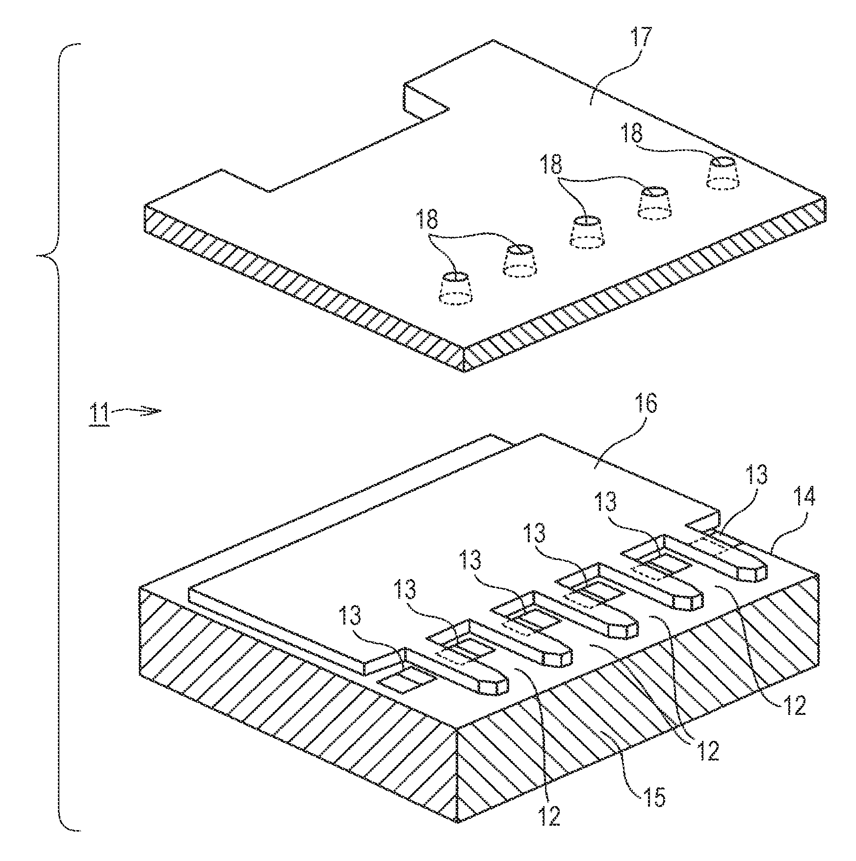
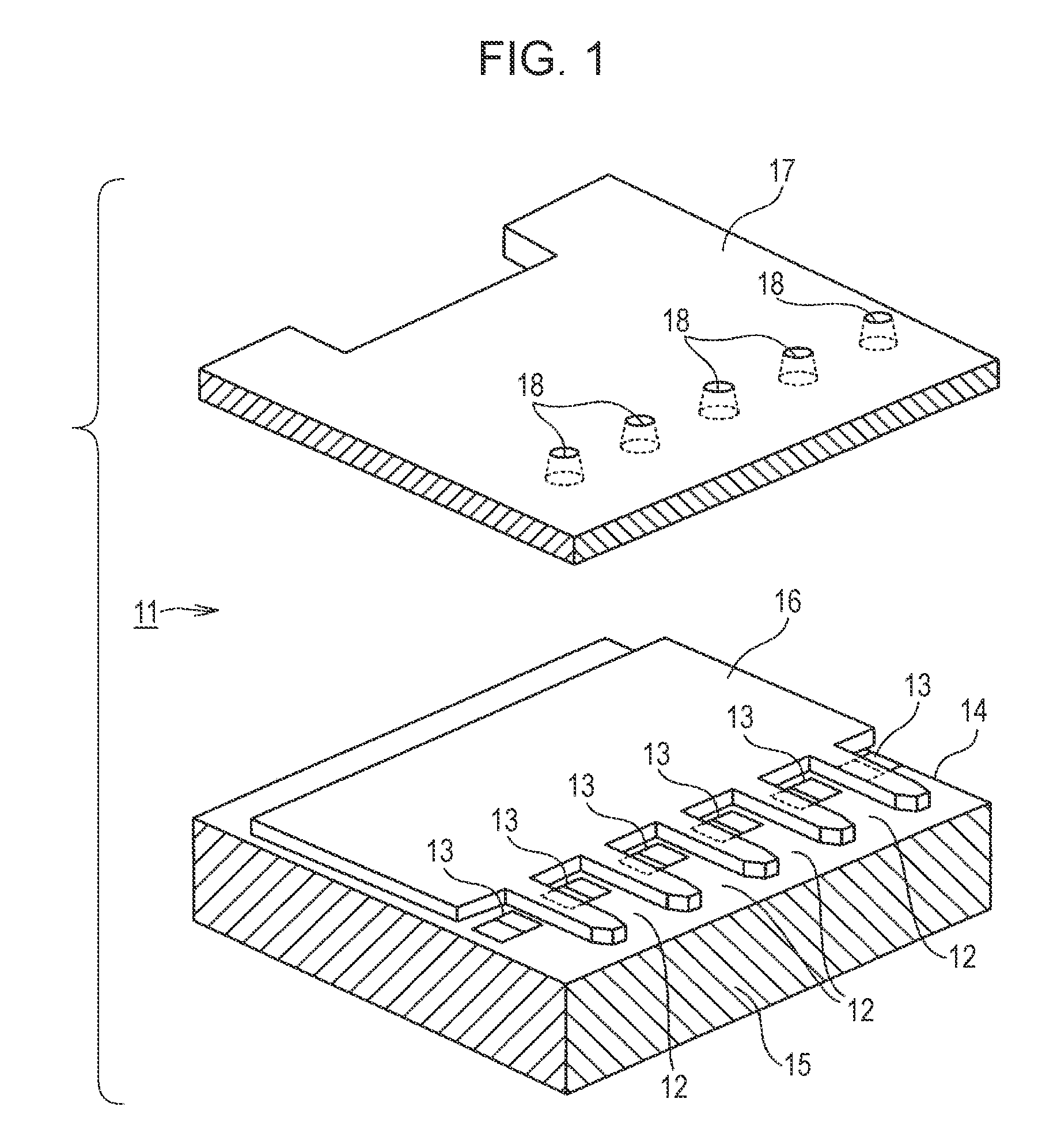
[0048]An embodiment of the present invention will now be described with reference to the drawings. In this embodiment, a liquid-ejecting head corresponds to inkjet head units 11 for an inkjet printer, as shown in FIG. 1. In addition, an ejection medium that is ejected by the inkjet head units 11 and is liquid at normal temperature is an ink in this embodiment. Furthermore, liquid cells for containing the ink are ink cells 12, and a trace amount (for example, several picoliters) of ink ejected from nozzles 18 in a droplet form is an ink droplet.

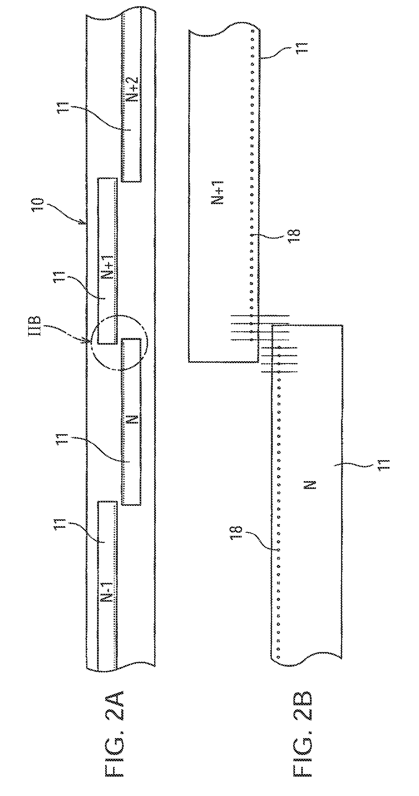
[0049]In this embodiment, the inkjet head units 11 are thermal inkjet head units including heat-generating resistors 13 serving as energy-generating elements. The heat-generating resistors 13 are formed by deposition on a surface of a semiconductor substrate 15 serving as a base member 14. The thermal inkjet head units 11 are arranged along the width of printing paper, as a recording medium, to constitute a thermal line head 10. In this embodi...


PUM


Abstract

A liquid-ejecting head includes a liquid cell that contains an ejection medium that is liquid at normal temperature, a nozzle for ejecting the ejection medium in the liquid cell, an energy-generating element for supplying ejection energy to the ejection medium in the liquid cell, and heating means for heating the liquid cell independently of the supply of the ejection energy to the ejection medium in the liquid cell. The energy-generating element is driven to eject the ejection medium from the nozzle in a droplet form. The heating means is supplied with a substantially direct current component to generate heat so that at least the temperature of the liquid cell is constantly maintained above the ambient temperature irrespective of whether the energy-generating element is driven.

Description

RELATED APPLICATION DATA[0001]This application is a divisional of U.S. patent application Ser. No. 11 / 359,192, filed Feb. 22, 2006, the entirety of which is incorporated herein by reference to the extent permitted by law. The present invention claims priority to Japanese Patent Application No. 2005-052179 filed in the Japanese Patent Office on Feb. 28, 2005, the entirety of which also is incorporated by reference herein to the extent permitted by law.BACKGROUND OF THE INVENTION[0002]The present invention relates to liquid-ejecting heads, liquid-ejecting devices, and liquid-ejecting methods for ejecting an ejection medium contained in liquid cells from nozzles in a droplet form by driving energy-generating elements, and also relates to ejection media for the liquid-ejecting heads. Specifically, the present invention relates to techniques for providing liquid-ejecting devices with high ejection stability and a significantly wide operating temperature range.[0003]Inkjet printers are on...

Claims


Application Information

Patent Timeline
Patent Type & Authority Applications(United States)
IPC IPC(8): B41J2/05
CPCB41J2/04528B41J2/04533B41J2/04563B41J2/0458B41J2/1408B41J2/04501
Inventor EGUCHI, TAKEOUSHINOHAMA, IWAO
Owner SONY CORP
Why Eureka
Try Eureka