Liquid ejection head, liquid ejection device and liquid ejection method

a liquid ejection device and liquid ejection technology, applied in printing, other printing apparatus, etc., can solve the problems of high drive voltage, extreme cost increase of a head and a device, and the inability to realize a device that is suited, and achieve the effect of high viscosity

Inactive Publication Date: 2010-04-06
KONICA MINOLTA INC
View PDF15 Cites 5 Cited by
  • Summary
  • Abstract
  • Description
  • Claims
  • Application Information

AI Technical Summary

Benefits of technology

[0018]Therefore, an objective of the invention is to provide a liquid ejection head wherein an electric field assist method that controls an amount of meniscus protrusion and controls ejection is used, a ejection surface is flat, meniscus forming drive can be switched with low voltage, electric field is concentrated effectively with impression of electrostatic voltage of low voltage, a liquid is ejected efficiently, and thereby, the fine pattern can be formed and a liquid of high viscosity can be ejected, a liquid ejection device and a liquid ejection method.

Problems solved by technology

When these problems are attempted to be solved by a conventional inkjet recording method, minimization of nozzles and improvement of liquid ejection force for ejecting high viscosity ink are needed, resulting in high drive voltage and extreme cost increase for a head and a device, which has prevented realization of a device that is suited to practical use.
However, when a flat liquid ejection head of this kind is used in the liquid droplet ejection technology of the electrostatic suction method, an extent of electric field concentration for a liquid in a nozzle and for a meniscus of a ejection hole portion is low, and it has been necessary to apply extremely high voltage as voltage to be applied between the liquid ejection head and the base materials, for obtaining necessary electrostatic suction force.
Compared with an inkjet recording method employing a conventional piezoelectric system or a thermal system, in these liquid ejection devices employing the electric field assist method, electrostatic suction force by electric field is not utilized to its maximum level although the ejection efficiency is satisfactory, thus, forming of the meniscus and ejection of a liquid droplet are not conducted efficiently, and when trying to meet the demands for fine pattern forming and ejection of high viscosity ink, drive voltage needs to be higher, resulting in a cost increase of a head and a device in the same way as in the conventional inkjet recording method, which has been a problem.
Further, when voltage to be applied is boosted for enhancing electrostatic suction force, dielectric breakdown is caused between a head and base materials, which sometimes makes it impossible to drive the device, which has also been a problem.
However, even in the case of the liquid ejection device employing the electric field assist method wherein pressure is generated by a transformation of a piezoelectric element, to protrude a liquid meniscus on an ejection hole of a nozzle, and electric field is concentrated selectively on the protruded meniscus to eject a liquid by electrostatic suction force, an action to draw out a meniscus by electrostatic suction force for forming a meniscus is poor because of poor electric field concentration, resulting in necessity of applying high voltage on pressure generating portion that is composed of piezoelectric element actuators such as piezoelectric elements, which has been a problem.
However, a large number of nozzles each being in a lightning rod shape having a height of about several tens μm need to be embedded toward the ejection surface side from the nozzle plate of the liquid ejection head, which makes the structure to be complicated, and lowers productivity.
Further, there has been a problem of poor operability that embedded nozzles are broken in the course of cleaning of the liquid ejection head.

Method used


Image

  • Liquid ejection head, liquid ejection device and liquid ejection method
  • Liquid ejection head, liquid ejection device and liquid ejection method
  • Liquid ejection head, liquid ejection device and liquid ejection method

Examples


example

Example 1

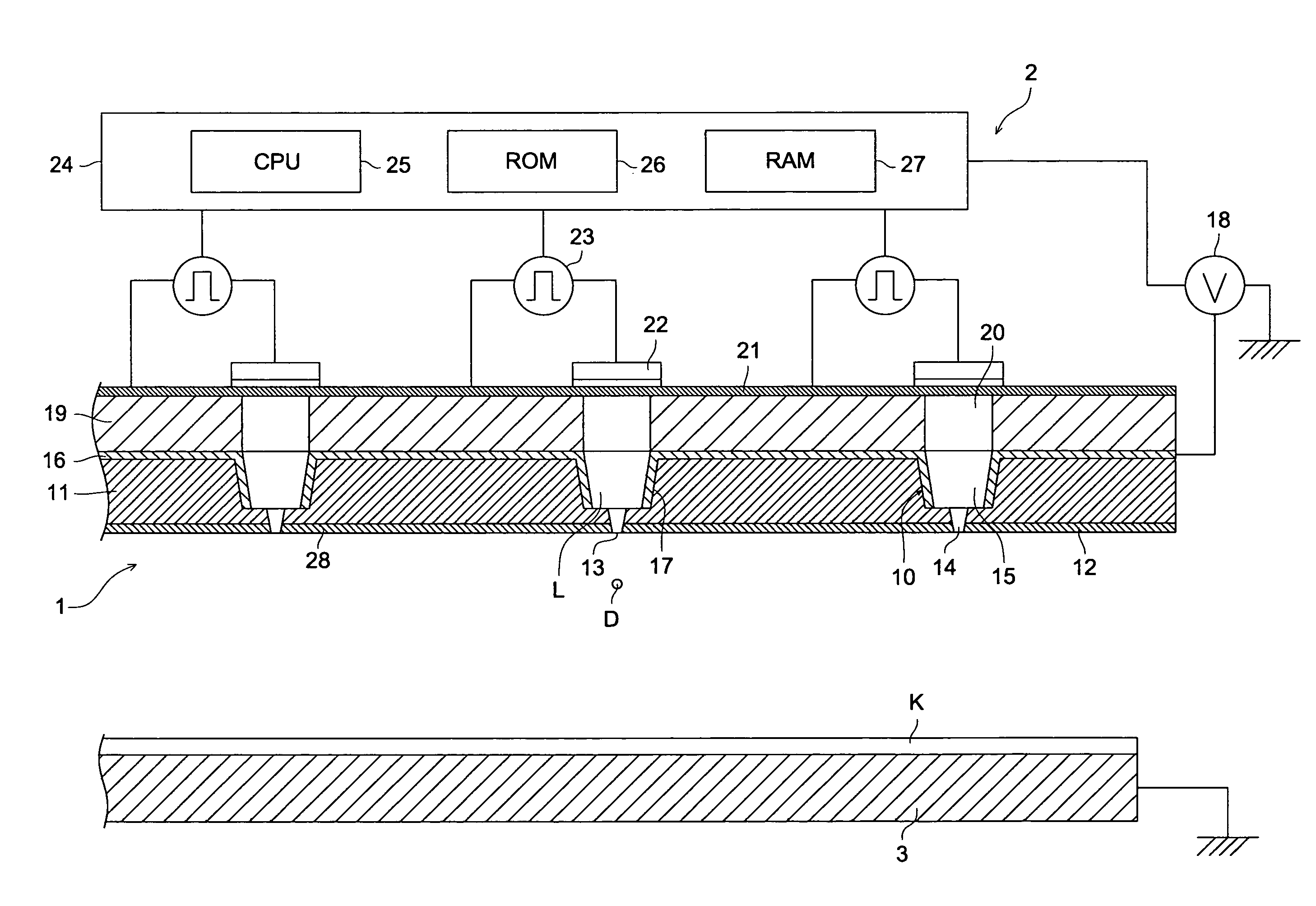
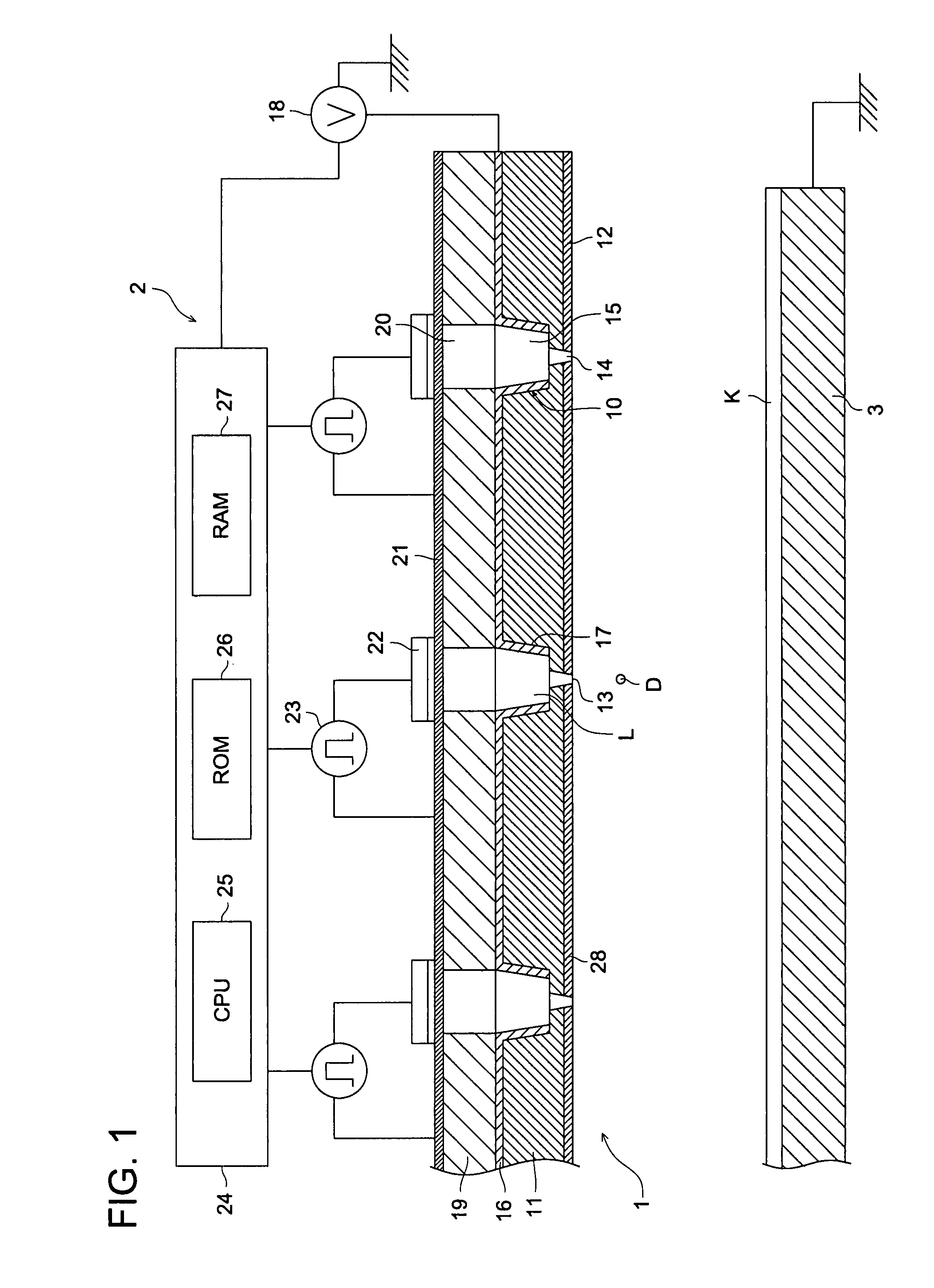
[0132]Nozzle plates 11 of liquid ejection head 2 of the present embodiment were actually prepared by using various types of materials, and whether liquid droplet D is ejected from ejection hole 13 of nozzle 10 or not was confirmed by ejecting on base material K.

[0133]The structure of the liquid ejection head 2 was made to be a single-step structure made under the same conditions as the aforesaid experiment conditions wherein a taper angle of nozzle 10 is 4° and small diameter portion 14 and large diameter portion 15 are continuous.

[0134]Further, liquid L1 was prepared as a conductive liquid that contains 52% by weight of water, 22% by weight of ethylene glycol, 22% by weight of propylene glycol, 3% by weight of dye (CI Acid Red 1) and 1% by weight of surfactant, while, liquid L2 was prepared as a conductive liquid wherein 3% by weight of dye (the same as the above) is contained in ethanol and liquid L3 was prepared as a liquid wherein Ag particles are dispersed in tetradeca...

example 2

[0140]Nozzle plates 11 of liquid ejection head 2 of the present embodiment were prepared by changing a thickness of nozzle plate 11 and a nozzle diameter variously, and whether the liquid L1 is ejected or not was confirmed by ejecting on base material K. Further, as a referential experiment, whether the liquid L1 is ejected or not was confirmed under the condition in which the liquid L1 was not ejected, by causing electrostatic voltage to be 3.0 kV.

[0141]Results of the experiments proved to be those shown in the following Table 2. Incidentally, nozzle plate 11 was formed by using polyethylene terephthalate, Lumirror (made by TORAY INDUSTRIES, INC.), described on Table 1.

[0142]

TABLE 2NozzlediameterNozzle plateElectrostaticEjecting of(μm)thickness (μm)voltage (KV)liquid101251.5G151251.5G201251.5NG201253G151001.5G15751.5G15501.5NG15503GG: GoodNG: Not Good

[0143]When comparing the results of the occasion where a thickness of nozzle plate 11 is 125 μm, it is understood from the results of...


PUM


Abstract

A liquid ejection head having: a nozzle for ejecting a liquid; a flat nozzle plate on which the nozzle is provided; a cavity to store the liquid to be ejected from an ejection hole of the nozzle; a pressure generating section which generates pressure on the liquid in the nozzle and forms a meniscus of the liquid in the ejection hole of the nozzle; an electrostatic voltage applying section which applies electrostatic voltage between a base material and the liquid in the nozzle and the cavity, and generates electrostatic suction force; and an operation control section which controls applying of the electrostatic voltage by the electrostatic voltage applying section, and controls applying of drive voltage to drive the pressure generating portion, wherein a volume resistivity of the nozzle plate is 1015 Ωm or more.

Description

CROSS REFERENCE TO RELATED APPLICATIONS[0001]This is a U.S. national stage of application No. PCT / JP2005 / 022442, filed on 07 Dec. 2005. Priority under 35 U.S.C. §119(a) and 35 U.S.C. §365(b) is claimed from Japanese Application No. 2004-367810, filed 20 Dec. 2004, the disclosure of which is also incorporated herein by reference.TECHNICAL FIELD[0002]The present invention relates to a liquid ejection head, a liquid ejection device and a liquid ejection method, and in particular, to a liquid ejection head of an electric field concentration type having a flat nozzle, a liquid ejection device employing the liquid ejection head and a liquid ejection method employing the aforesaid liquid ejection head and the liquid ejection device.BACKGROUND[0003]In recent years, with a background of development of a trend toward high-definition of image quality in inkjet and expansion of a range of application thereof in an industrial use, demands for fine pattern forming and ejection of high viscosity i...

Claims


Application Information

Patent Timeline
Patent Type & Authority Patents(United States)
IPC IPC(8): B41J2/06
CPCB41J2/04576B41J2/04581B41J2/06B41J2/14233B41J2/04588B41J2002/14475
Inventor UENO, NOBUHIRONISHI, YASUOYANATA, ATSURO
Owner KONICA MINOLTA INC
Why Eureka
Try Eureka