Gas bearing and method of manufacturing the same

a technology of gas bearings and bearings, which is applied in the direction of bearings, shafts, laser beam welding apparatuses, etc., can solve the problem of needing a very small jet diameter

Active Publication Date: 2012-01-26
DUPONT RALF +1
View PDF18 Cites 5 Cited by
  • Summary
  • Abstract
  • Description
  • Claims
  • Application Information

AI Technical Summary

Benefits of technology

[0025]The method may include rotating the bearing housing relative to the laser beam about the shaft bore axis, whereby a predetermi

Problems solved by technology

Such size reduction results in a need for very small jet diameters.
In particular, any advantage associated with manufacturing jets as separate components is b

Method used


Image

  • Gas bearing and method of manufacturing the same
  • Gas bearing and method of manufacturing the same
  • Gas bearing and method of manufacturing the same

Examples


Embodiment Construction

; FURTHER OPTIONS AND PREFERENCES

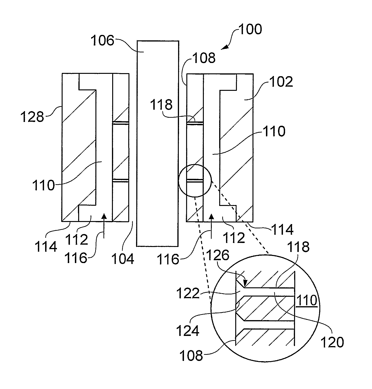
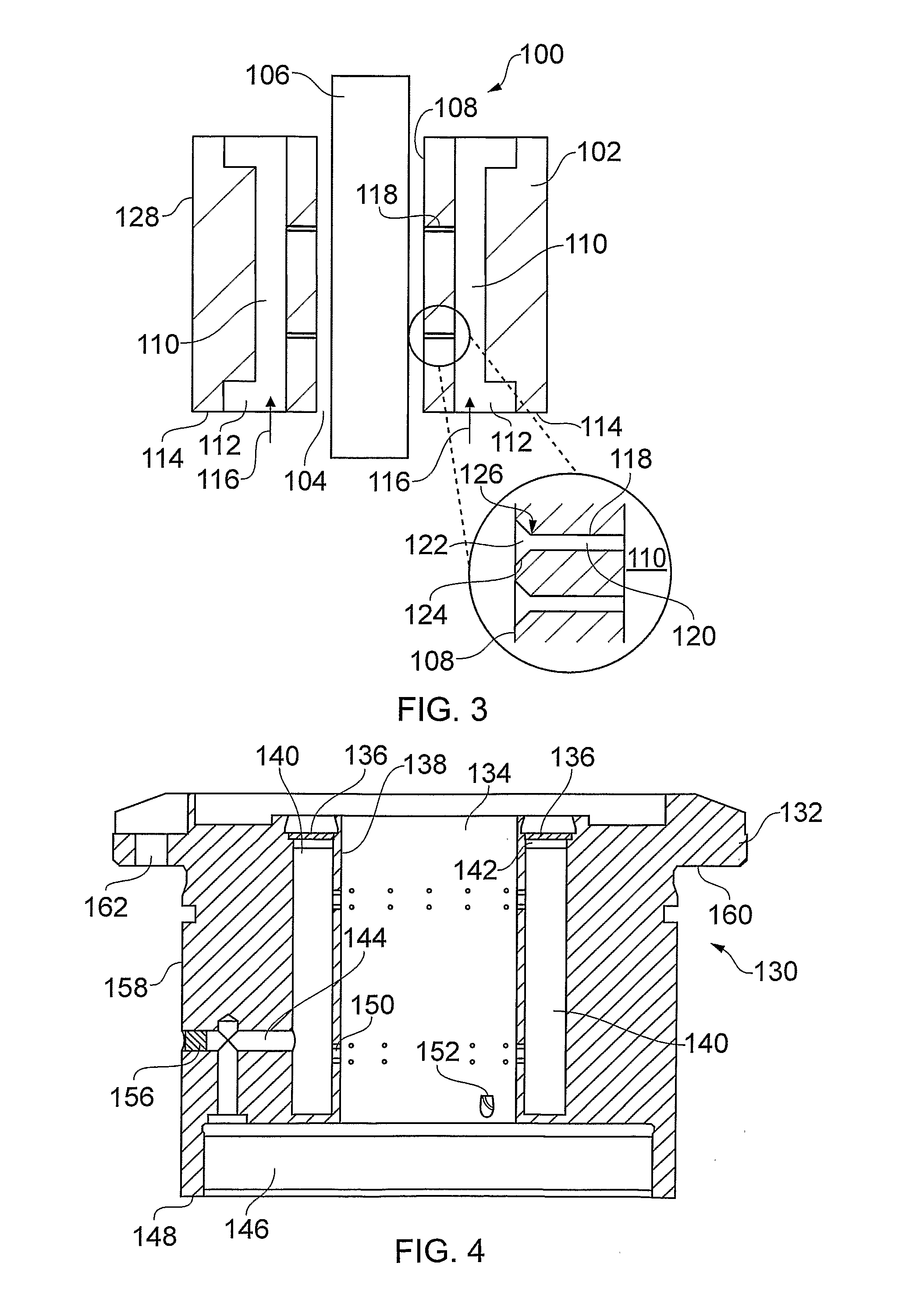
[0042]FIG. 3 shows a schematic cross-section of a journal gas bearing 100 that is an embodiment of the invention. The gas bearing 100 comprises a bearing housing 102 having a shaft bore 104 formed (e.g. mechanically drilled) through it. A shaft 106 mates with the bearing housing 102 by being received along its axis in the shaft bore 104. A bearing surface 108, which defines the shaft bore 104, has a diameter greater than the diameter of the shaft 106 so that an annular gap exists between the two.

[0043]The bearing housing 102 contains a plurality of axially extending chambers 110. As shown in FIG. 3, the chambers 110 each have an opening 112 formed at an axial end 114 of the bearing housing 102. The openings 112 may be arranged to receive pressurised gas from a gas supply as indicated by arrows 116. The axial extending chambers 110 thus comprise a pressurisable space contained in the bearing housing 102.

[0044]A plurality of laser drilled capillaries 1...


PUM

PropertyMeasurementUnit
Pressureaaaaaaaaaa
Circumferenceaaaaaaaaaa

Abstract

A gas bearing (100) having pressurised axially extending chambers (110) in a housing (102) having a shaft bore (104) therein, the axially chambers (110) being in fluid communication with a bearing surface (108) that defines the bore via laser-drilled capillaries (118). The end (122) of each laser-drilled capillary at the bearing surface (108) is flared such that the narrowest portion of the capillary is set back from the bearing surface (108). This shape can ensure that the load carrying function of the bearing (100) does not fail during shaft eccentricity by ensuring that pressure restriction must happen within the capillary and not the gap being shaft and bearing surface. The bearing surface may face in an axial and/or radial direction with respect to the shaft. The axial chambers may be pressurised axially such that the outer circumference of the housing is unbroken and hence usable for other purposes.

Description

FIELD OF THE INVENTION[0001]The invention relates to non-self-acting gas bearings for high speed relative rotation between two mating components.BACKGROUND TO THE INVENTION[0002]To provide the ability to generate a restoring force to compensate for non-zero shaft eccentricity in a non-self-acting bearing, it is known that a restriction of the passageway from a supply pressure to the bearing surface, e.g. using a plurality of jets, is needed.[0003]Each jet restricts the supply pressure to an intermediate pressure that is also dependent on the bearing gap width (i.e. distance between the bearing surface and the shaft) at the jet. The smaller the bearing gap width the higher the intermediate pressure. Under concentric conditions the intermediate pressures created by diametrically opposed jets is equal by symmetry. However, if the axis of the shaft is displaced from the axis of the bore (i.e. non-zero eccentricity) the intermediate pressure at a jet with a smaller bearing gap width will...

Claims


Application Information

Patent Timeline
IPC IPC(8): F16C32/06B23K26/38
CPCF16C33/1005F16C32/0622F16C32/0685F16C32/0696F16C2220/60
Inventor DUPONT, RALF
Owner DUPONT RALF
Why Eureka
Try Eureka