Ultraviolet sanitation device

Inactive Publication Date: 2005-02-03
TENNANT COMPANY
View PDF99 Cites 92 Cited by
  • Summary
  • Abstract
  • Description
  • Claims
  • Application Information

AI Technical Summary

Benefits of technology

[0005] The present invention generally relates to a sanitation device for sanitizing surfaces. In accordance with one embodiment of the invention, the sanitization device includes a mobile body and a source of UV radiatio

Problems solved by technology

Unfortunately, such chemicals can be hazardous requiring the user to take safety precautions before handling the chemicals,

Method used


Image

  • Ultraviolet sanitation device
  • Ultraviolet sanitation device
  • Ultraviolet sanitation device

Examples


Embodiment Construction

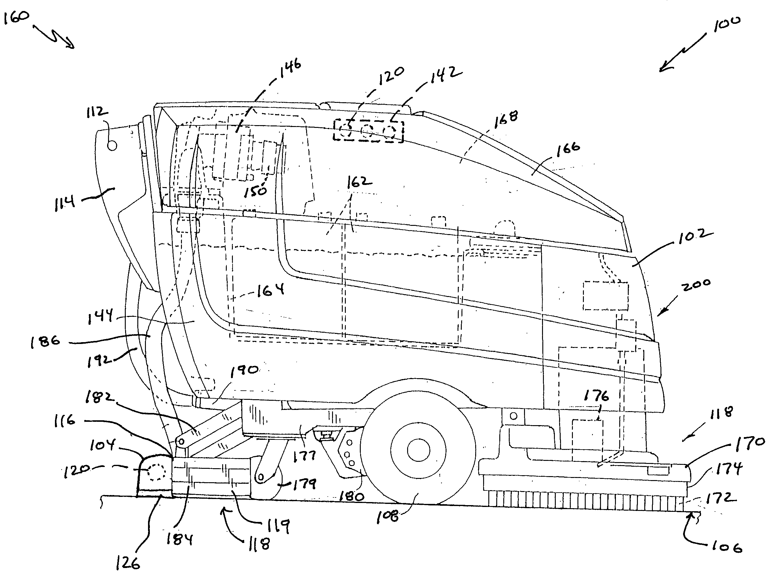
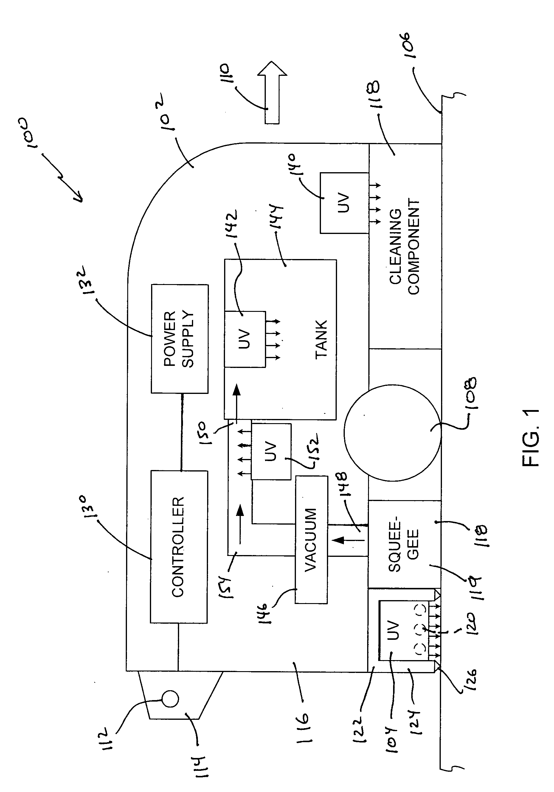
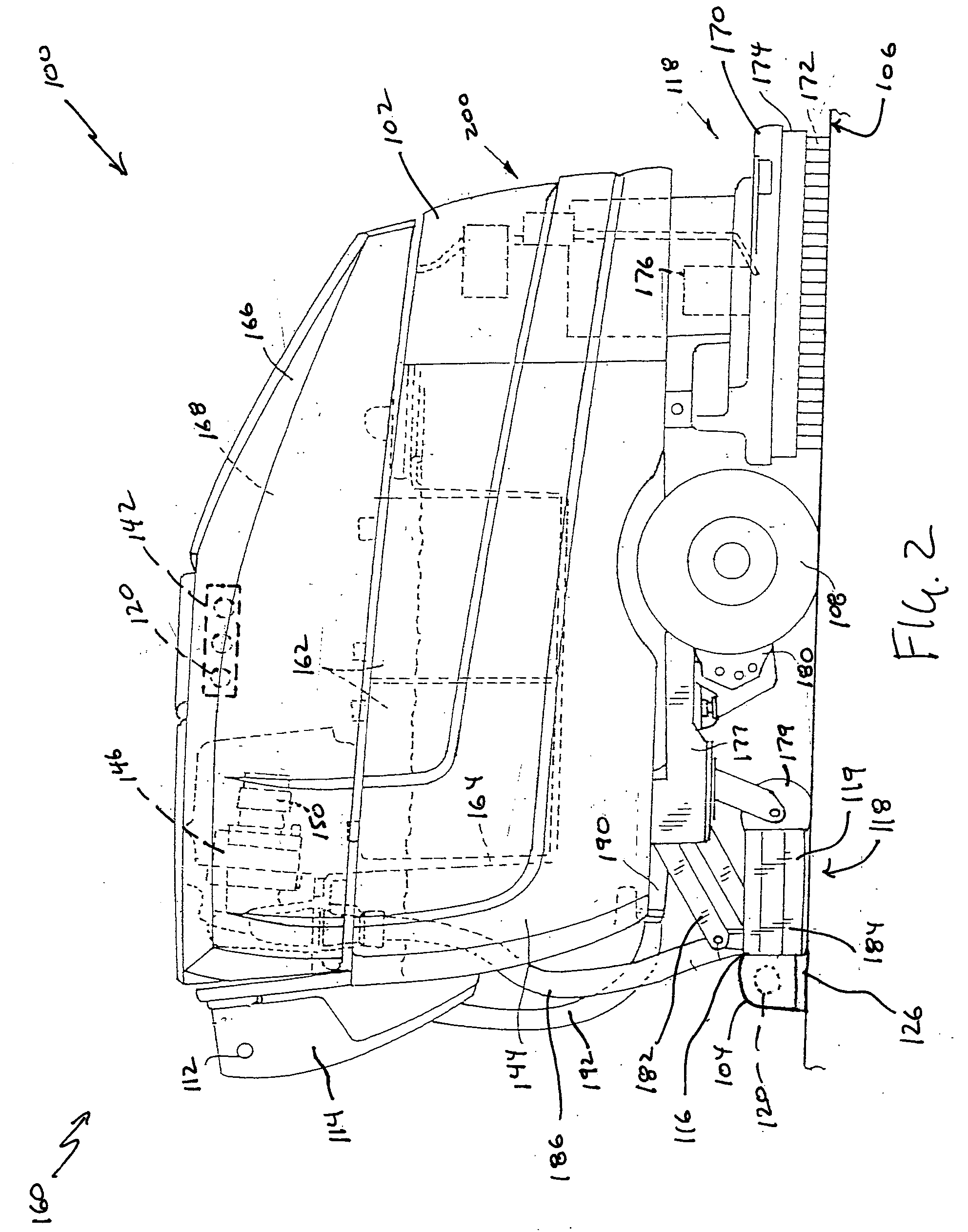
[0018] The present invention generally relates to a sanitization device that utilizes a source of UV radiation to provide a means for sanitizing a surface. As will be discussed below in greater detail, embodiments of the sanitization device include a source of UV radiation in combination with a mobile body, or a housing for handheld operation. Additional embodiments of the present invention relate to methods of sanitizing surfaces using the sanitization devices of the present invention.

[0019] UV radiation is generally identified as having three ranges: UV-A covering wavelengths of 315 nanometers (nm) and higher, UV-B covering wavelengths of 280-315 nm and UV-C covering wavelengths of 280 nm and lower. It has been determined that microorganisms can be inactivated by the UV radiation having wavelengths in the UV-C range, particularly wavelengths of 240-260 nm. UV radiation does not necessarily kill the target organisms, instead the radiation alters the cell DNA so that the organisms ...


PUM

PropertyMeasurementUnit
Wavelengthaaaaaaaaaa
Speedaaaaaaaaaa
Distanceaaaaaaaaaa

Abstract

A sanitation device includes a mobile body, a surface cleaning component, and a source of UV radiation. The surface cleaning component and the source of UV radiation are mounted to the mobile body, which is configured to travel over a surface. The surface cleaning component is configured to engage the surface and the source of UV radiation is configured to direct UV radiation to the surface.

Description

[0001] The present application is based on and claims the benefit of U.S. provisional patent application Ser. No. 60 / 491,181, filed Jul. 30, 2003, which is incorporated herein by reference in its entirety.FIELD OF THE INVENTION [0002] The present invention is generally directed to a sanitation device and, more particularly, to a sanitation device that includes a source of ultraviolet (UV) radiation that is used to sanitize a surface. Additional embodiments of the present invention are directed to methods of sanitizing surfaces using the device. BACKGROUND OF THE INVENTION [0003] There are many different types of surface cleaners that are configured for cleaning various surfaces such as, for example, streets, hard floors, and carpet. Examples of such cleaning machines are disclosed in U.S. Pat. Nos. 6,162,542, 6,585,827, 6,671,925, 6,705,332, and 6,735,812, which are assigned to Tennant Company of Minneapolis, Minn. and are incorporated herein by reference in their entirety. Such sur...

Claims


Application Information

Patent Timeline
IPC IPC(8): A47L11/283A47L11/30A47L11/33A61L2/10A61L2/24E01H1/04
CPCA47L11/283A47L11/305A47L11/33E01H1/042A47L11/4097A61L2/10A61L2/24A47L11/405
Inventor FIELD, BRUCE F.POULIOT, JOSEPH L.
Owner TENNANT COMPANY
Why Eureka
Try Eureka