
Automotive air bag device

Inactive Publication Date: 2005-02-03
HONDA MOTOR CO LTD
View PDF33 Cites 5 Cited by
  • Summary
  • Abstract
  • Description
  • Claims
  • Application Information

AI Technical Summary

Benefits of technology

[0012] Then, an object of the invention is to provide an automotive air bag device which can deploy an air bag more uniformly.

Problems solved by technology

The deployment direction of a gas bag distal end portion 110 is caused to deviate (for example, to the diagonally left front), whereby there may be caused a risk that the deployment of the gas bag becomes incomplete.
Thereby there may be caused a risk that the gas bag 101 cannot deploy into a uniform parabola.

Method used


Image

  • Automotive air bag device
  • Automotive air bag device
  • Automotive air bag device

Examples


Embodiment Construction

[0041] Embodiments of the invention will be described based on the accompanying drawings. Note that the drawings are to be seen in a direction in which reference numerals stand properly.

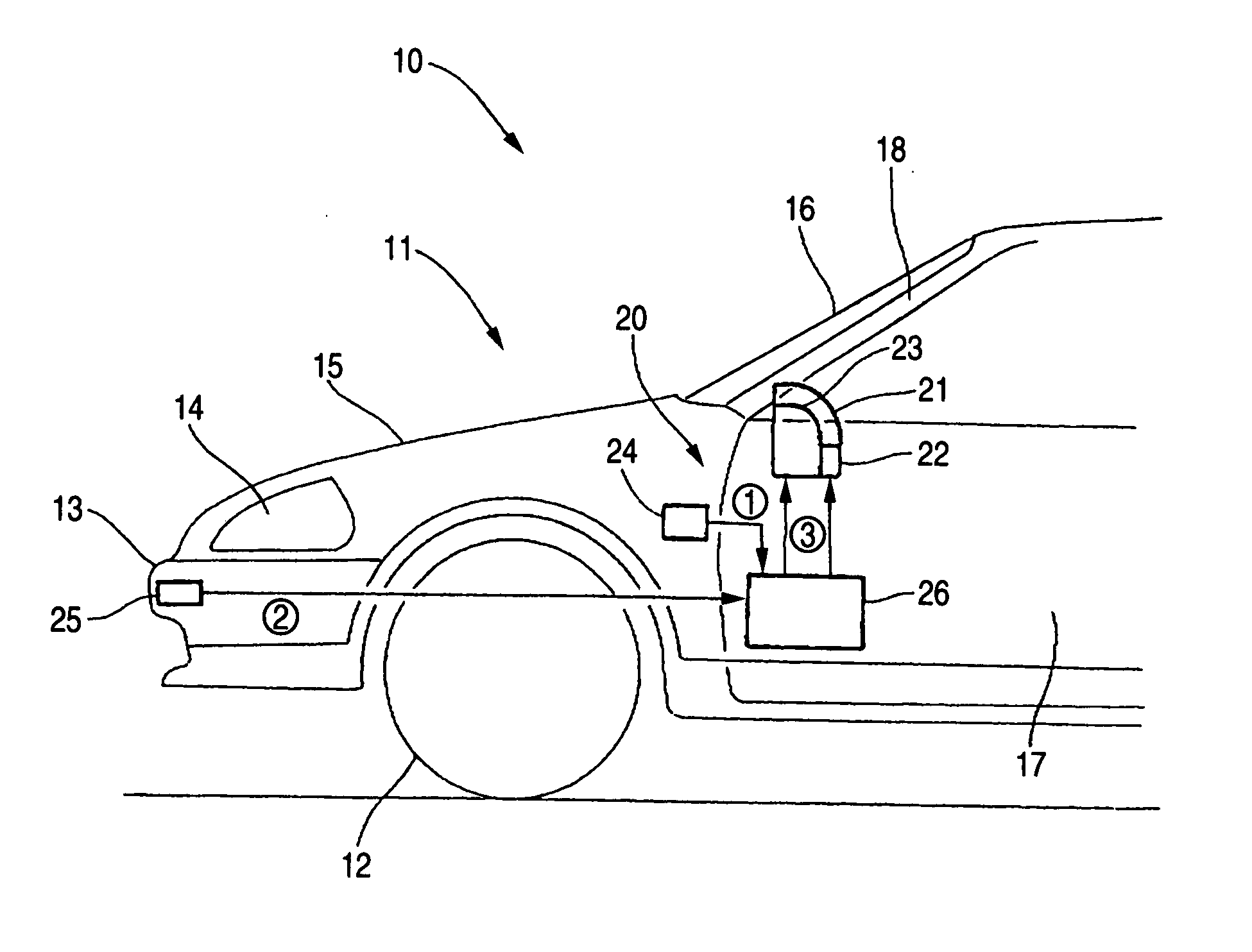
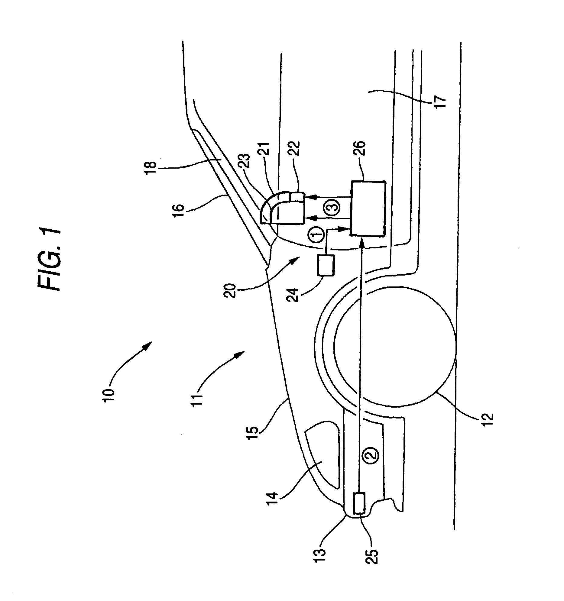
[0042]FIG. 1 shows an automotive air bag system into which an air bag device according to the invention is incorporated, in which reference numeral 10 denotes an automobile, reference numeral 11 denoting a vehicle body, reference numeral denoting a front wheel, reference numeral 13 denoting a front bumper, reference numeral 14 denoting a headlamp, reference numeral 15 denoting a bonnet, reference numeral 16 denoting a windscreen, reference numeral 17 denoting a door, and reference numeral 18 denoting a front pillar.

[0043] An air bag system 20 includes a primary driver air bag device 21 and a secondary driver air bag device 22 which are both designed to protect the driver, a front seat passenger air bag device 23 for protecting a front seat passenger, an acceleration sensor 24 for detecting an impac...


PUM


Abstract

An automotive air bag device has a panel, a folded bag installed in a deeper portion behind the panel, a cover provided in the panel and a connecting member that connects a vehicle body side with the cover. The air bag is inflated by virtue of a gas pressure to push open the cover provided so that the air bag deploy into a passenger compartment, the cover is mounted in the panel so as to be separated from the panel when the air bag is inflated and the connecting member controls a protrusion of the air bag into a passenger compartment.

Description

[0001] The present invention claims foreign priority to Japanese patent application No. JP-2003-205389, filed on Aug. 1, 2003, the contents of which is incorporated herein by reference. BACKGROUND OF THE INVENTION [0002] 1. Field of the Invention [0003] The present invention relates to an improved automotive air bag device. [0004] 2. Description of the Related Art [0005] Conventionally, there has been known, as an automotive air bag device, an air bag device installed in a part of a steering wheel (for example, See Japanese Utility Model Examined Publication JP-UM-Y-54-1711 pages 2 to 3, FIG. 1). [0006]FIG. 6 is incorporated herein to show FIG. 1 of the JP-UM-Y-54-1711. However, reference numerals are changed. [0007] Reference numeral 101 denotes a gas bag, reference numeral 102 denoting a bag housing case, reference numeral 103 denoting a lid, reference numeral 104 denoting a gas bag protruding opening, reference numeral 106 denoting a lining, reference numeral 107 denoting an elon...

Claims


Application Information

Patent Timeline
IPC IPC(8): B60R21/16B60R21/20B60R21/205B60R21/216B60R21/233
CPCB60R21/206B60R21/215B60R21/216B60R2021/23382B60R21/2338B60R2021/23169B60R21/233
Inventor KAI, TAKESHIKUNITAKE, YUKIHIROISHIZUKA, YUJI
Owner HONDA MOTOR CO LTD
Learn More