
Printing through collaboration of image forming apparatuses

Inactive Publication Date: 2005-02-10
RICOH KK
View PDF8 Cites 35 Cited by
  • Summary
  • Abstract
  • Description
  • Claims
  • Application Information

AI Technical Summary

Benefits of technology

[0016] According to at least one embodiment of the invention, the use of an image forming apparatus having limited functionality achieves significant const reduction, yet sophisticate printing using a desired function is made possible at the inexpensive image forming apparatus having limited functionality by delegating the function to another image forming apparatus having sophisticated functionality inclusive of the desired function.

Problems solved by technology

In general, MFPs are bulkier compared to printers having only a printing function, and thus require larger installation space.
Also, MFPs that operate at high speed and offer sophisticated functions tend to generate large operation noise.
Because of this, users tend to dislike having an MFP installed close to their desk spaces in an office environment in which MFPs and PC (personal computers) are connected through a network.
If an MFP connected to a network is located at a remote location, however, it requires excess labor and time for users to go to such a location, fetch printouts, and return to their own desks.
In a home office, a satellite office, or a hotspot where access to the Internet is available, how to provide an outputting device such as a printer becomes an issue.
When an MFP or a printer needs to be installed at home offices, it is difficult to provide each individual with an image forming apparatus having sophisticated functions due to heavy investment costs that would be required.
As a result, the functionality of such equipment needs to be limited to some extent.
At a home office, a satellite office, or a hotspot, however, it does not make sense to print to a sophisticated apparatus situated at a faraway site.
In the offices of a network environment, printing to a sophisticated apparatus situated at a remote location creates the problem of excess labor and time as well as the problem of confidentiality.
This simply results in a trivial configuration having a low cost and low functionality.

Method used


Image

  • Printing through collaboration of image forming apparatuses
  • Printing through collaboration of image forming apparatuses
  • Printing through collaboration of image forming apparatuses

Examples


Embodiment Construction

[0029] In the following, embodiments of the present invention will be described with reference to the accompanying drawings.

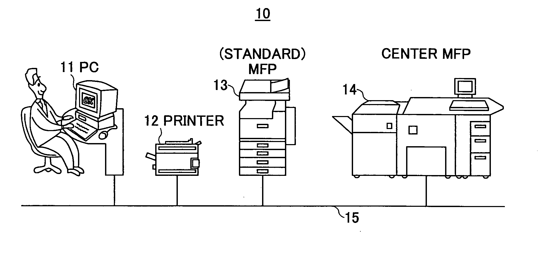
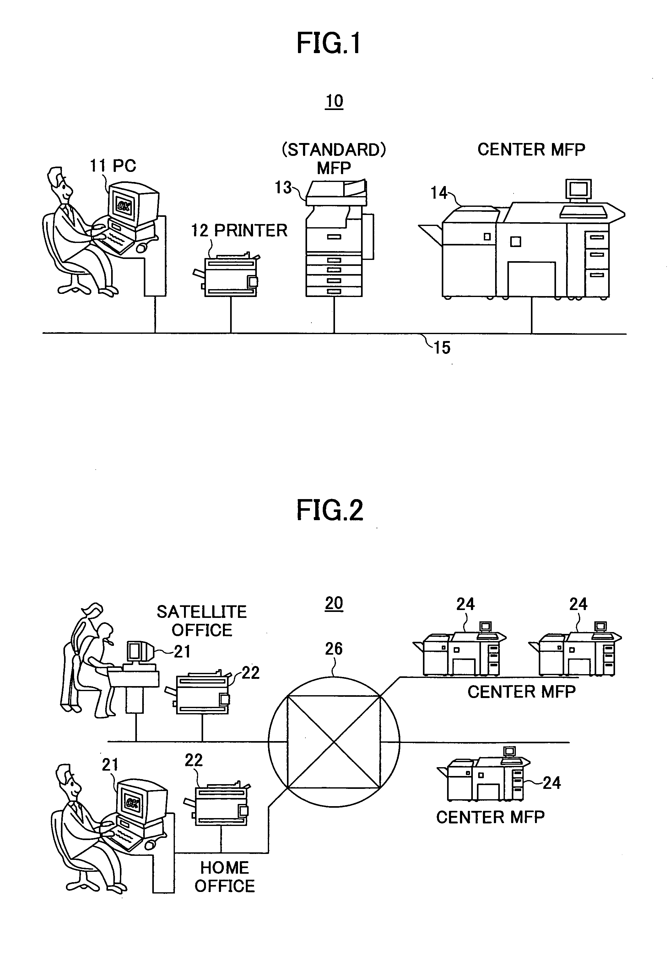
[0030]FIG. 1 is an illustrative drawing showing an image forming system according to the present invention. In FIG. 1, an image forming system 10 includes a personal computer (PC) 11, a printer 12 situated in the proximity of the personal computer 11, a standard MFP 13 having standard functionality and the functions of a facsimile, a printer, a copier, a scanner, and the like, a center MFP 14 having sophisticated functionality and provided with a peripheral device having a finishing function and the like, and a LAN (local area network) 15 for connecting these apparatuses together. The printer 12 may be provided with only a printer function, or may be an MFP provided with a facsimile function, a copier function, a scanner function, and the like in addition to the printer function. The printer 12 may generally be provided to each user, and, thus, may be a small-...


PUM


Abstract

An image forming apparatus, which has hardware for image printing and at least one data processing function for use in the image printing, and is connected to a network, includes an analysis unit configured to analyze data received from the network, a processing unit configured to perform the data processing function according to a result of the analysis by the analysis unit thereby to generate print data from the received data, and a transmission unit configured to transfer the print data to another image forming apparatus connected through the network.

Description

BACKGROUND OF THE INVENTION [0001] 1. Field of the Invention [0002] The present invention generally relates to image forming apparatuses, image forming methods, and image forming systems, and particularly relates to an image forming apparatus, an image forming method, and an image forming system for use in a configuration in which a plurality of image input / output apparatuses are connected together to perform a collaborative printing operation. [0003] 2. Description of the Related Art [0004] In recent years, an image forming apparatus that consolidates a plurality of machine-specific functions such as those of a facsimile machine, a printer, a copier, a scanner, etc., into one device has become widely known. This image forming apparatus (MFP: multifunction peripheral) is provided with a display unit, a print unit, an imaging unit, etc., in one device, and is also provided with four applications corresponding to a facsimile machine, a printer, a copier, and a scanner, respectively. S...

Claims


Application Information

Patent Timeline
IPC IPC(8): G06F3/12B41J29/38G06K15/02H04N1/00
CPCG06F3/1204G06F3/124G06K15/1859G06F3/1286G06K15/02G06F3/1261
Inventor MOROI, SHOHHEI
Owner RICOH KK
Learn More